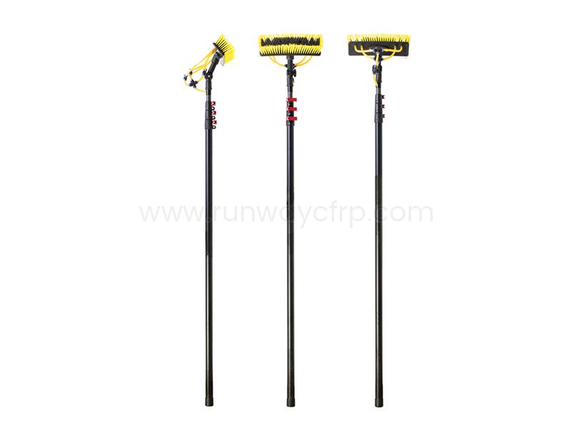
When I specify a precision diameter carbon tube, I am controlling more than the tube’s outside measurement. Diameter accuracy affects fit, alignment, load transfer, vibration behavior, joint stress, and assembly reliability. The outer diameter, inner diameter, wall thickness, roundness, straightness, and dimensional tolerance must work together because an error in one feature can change the performance of the entire assembly.
For engineering projects, a carbon fiber tube is often part of a larger mechanical system rather than an isolated component. It may support a bearing, receive an insert, connect two structural members, guide a telescoping section, or transfer bending and torsional loads through a bonded joint. In each case, the tube diameter determines how accurately neighboring parts locate and how forces move through the assembly.
A nominal diameter alone is not enough for design approval. I also need the specified tolerance, fit class, geometric tolerances, inspection method, and assembly-level acceptance criteria. A tube marked “50 mm diameter” could still be unsuitable if its actual diameter varies beyond the mating component’s clearance, if the cross-section is oval, or if the tube has excessive runout along its length.
Diameter precision is especially important in aerospace structures, robotics, inspection equipment, optical supports, lightweight frames, and carbon fiber tube assemblies with bonded or mechanical joints. In these applications, dimensional errors can produce rework, uneven adhesive thickness, local stress concentration, vibration, misalignment, or premature joint failure.
Precision diameter describes the controlled dimensional condition of a tube’s inside diameter, outside diameter, and related geometry. It includes the measured diameter value, the permitted variation around the nominal dimension, and the consistency of the surface along the tube length. It also includes roundness, straightness, concentricity, and runout when those characteristics affect the intended function.
The distinction between the main dimensions is straightforward:
Outer diameter (OD): The external measurement that controls external fit, clamps, guides, bearing seats, and structural envelope.
Inner diameter (ID): The internal opening that controls inserts, shafts, cables, fluid passages, and telescoping interfaces.
Wall thickness: The difference between OD and ID divided by two, assuming a circular section.
Tolerance: The permitted dimensional variation from the specified nominal value.
Geometric tolerance: The permitted variation in form, position, orientation, or runout.
For example, a tube with a 40 mm OD and a 34 mm ID has a nominal wall thickness of 3 mm. If the OD and ID vary independently, the wall may not remain uniformly 3 mm around the circumference. That variation can influence local stiffness, bonding area, buckling resistance, and the way the tube responds to cyclic loading.
The first effect of diameter accuracy is mechanical fit. If the tube is inserted into a socket, sleeve, bearing housing, or connector, the difference between the mating dimensions determines whether the assembly is too tight, too loose, or acceptable.
An interference fit may create excessive hoop stress in the composite wall, especially when the tube has limited radial strain capacity. A clearance fit may allow movement, adhesive gaps, fretting, or impact during vibration. For bonded joints, excessive clearance can create a thick adhesive layer that changes cure behavior and reduces predictable load transfer.
I recommend defining the actual assembly condition rather than specifying the tube in isolation. The drawing should identify the mating part, the intended clearance or interference, the adhesive system if applicable, and the maximum permitted variation after surface preparation.
Diameter errors can shift the position of connected parts. This is important when carbon fiber tubes support optical devices, sensors, rotating shafts, linear guides, or articulated mechanisms. A tube that is dimensionally acceptable at one end but offset at the other can introduce angular misalignment across its length.
Straightness and runout must therefore be reviewed with diameter. A circular tube with a correct average OD may still fail an assembly requirement if its centerline is not sufficiently straight. For long tubes, even a small angular deviation can produce a larger positional error at the far end.
The tube diameter also affects how loads enter and leave the composite structure. Larger diameters generally increase the second moment of area for bending when wall thickness and material distribution are considered, but the final result depends on laminate design, fiber orientation, wall thickness, support conditions, and loading direction.
At a joint, diameter accuracy determines contact area and load distribution. If an insert does not sit concentrically, the load may transfer through one side of the wall instead of around the full circumference. That can create local compression, peeling stress in the adhesive, and damage near the joint boundary.
Loose fits and inconsistent wall geometry can increase vibration response. A small clearance may permit impact or micro-motion, while ovality can cause periodic contact in rotating or sliding systems. Changes in wall thickness can also shift local stiffness and natural frequencies.
For precision assemblies, I treat diameter, roundness, straightness, and joint fit as one dynamic design problem. A tube may meet a static strength requirement but still perform poorly if the assembly has excessive movement or an unexpected resonant response.
Carbon fiber tube dimensional tolerances depend on the manufacturing method, tube size, laminate construction, tooling, curing process, finishing operation, and inspection method. There is no single tolerance value that applies to every carbon fiber tube.
For early engineering work, I often separate tolerances into four levels:
| Specification element | Purpose | Example engineering question |
|---|---|---|
| Nominal dimension | Defines the target size | Is the OD 25 mm, 40 mm, or 60 mm? |
| Size tolerance | Controls dimensional variation | How far may the actual OD or ID deviate? |
| Geometric tolerance | Controls form and position | How much ovality, straightness, or runout is acceptable? |
| Assembly acceptance | Confirms functional fit | Does the tube enter the mating part and maintain alignment? |
Illustrative tolerances should not be treated as universal supplier commitments. A general-purpose tube might be acceptable with a relatively broad OD variation, while a machined interface may require a much narrower range. If an engineer needs a finished OD of 50.00 mm with a tolerance of ±0.05 mm, the manufacturer must confirm that the process, tooling, finishing, and inspection system can repeatedly produce that condition.
I also distinguish between average dimensional accuracy and batch consistency. A supplier may produce one tube within specification while the lot varies significantly. For production programs, the drawing should define sampling frequency, inspection records, and the response required when a measurement falls outside the permitted range.
The custom carbon fiber tube inner and outer diameter should be selected together because changing one dimension affects wall thickness and mechanical behavior. A larger OD with the same ID increases wall thickness, while a larger ID with the same OD reduces it. Neither change is automatically beneficial.
A larger OD may improve bending stiffness, increase the external bonding surface, or provide more space for fasteners and clamps. However, it may also exceed the available installation envelope or increase joint mass. A larger ID may accommodate a larger shaft, cable bundle, or insert, but reducing wall thickness can lower local crushing resistance and increase sensitivity to impact.
The following relationships should be checked during design:
OD to ID relationship: Determines nominal wall thickness and available internal clearance.
Wall thickness uniformity: Influences stiffness, buckling, joint compression, and damage tolerance.
OD tolerance: Controls external interfaces, clamps, guides, and structural envelopes.
ID tolerance: Controls inserts, shafts, sleeves, and telescoping components.
Concentricity: Determines whether the wall and load path remain balanced around the centerline.
Roundness: Determines whether circular mating parts contact evenly.
Straightness: Determines alignment over the full tube length.
For a tube used as a compression member, diameter accuracy should be evaluated alongside laminate stability and end restraint. A small geometric imperfection can contribute to eccentric loading and reduce the practical buckling margin. The final assessment should use the actual boundary conditions rather than relying only on nominal dimensions.
When I evaluate a supplier, I review the manufacturing route before discussing a target tolerance. Runway, for example, identifies filament winding, roll wrapping, pultrusion, and CNC machining support among its composite production capabilities. These processes are suited to different tube geometries, laminate structures, production quantities, and finishing requirements.
Filament winding can provide controlled fiber placement around cylindrical forms and is useful when hoop strength, pressure resistance, or repeatable tubular construction is important. Roll wrapping supports layered laminate construction around a mandrel and allows designers to combine axial, angled, and hoop-oriented plies. Pultrusion is suited to continuous profiles and repeated cross-sections, but the finished tolerance and cut quality must be reviewed for the intended interface.
Machining may be required when the as-cured tube does not provide the necessary final diameter. However, machining removes material and can expose fibers, alter the surface condition, or reduce wall thickness if not controlled. A supplier should explain the machining allowance, tooling method, dust control, edge treatment, and final inspection process.
Fiber orientation affects both structural performance and dimensional stability. Axial fibers support longitudinal stiffness and tensile loading, while angled and hoop fibers contribute to torsional, transverse, and radial behavior. The laminate must be designed around the applied loads and the way the tube is supported.
A tube with a precise diameter but unsuitable fiber orientation may still fail in service. Conversely, a structurally appropriate laminate may be difficult to hold within a tight tolerance if the cure cycle, resin content, or tooling control is inconsistent. Dimensional requirements should therefore be reviewed with the laminate schedule rather than treated as a separate purchasing detail.
The mandrel establishes the internal geometry during manufacturing. Its diameter, surface condition, thermal expansion, release system, and alignment all influence the final ID and wall distribution. If the mandrel is worn, misaligned, or not suitable for the cure temperature, the tube may develop taper, ovality, or inconsistent internal dimensions.
Curing also affects dimensional stability. Temperature, pressure, resin flow, consolidation, and post-cure conditions can change shrinkage and residual stress. I ask suppliers how they monitor the cure cycle and how they control dimensional changes between the cured state and the finished inspection state.
I use the following sequence to convert an application requirement into a usable tube specification.
First, identify what the tube must connect to. Record whether the interface is bonded, clamped, bolted, press-fitted, telescoping, or supported by a bearing or bushing. State the mating component’s size and material because aluminum, steel, polymer, and composite interfaces may require different fit conditions.
Next, specify the nominal OD and ID independently. Do not describe the tube only as “approximately 40 mm.” Instead, define the target dimension, permitted variation, measurement location, and whether the tolerance applies before or after machining.
Specify straightness, roundness, concentricity, and runout when they affect the application. For a short bonded sleeve, diameter and roundness may be the main concerns. For a long optical or robotic boom, straightness and centerline runout may be equally important.
Finally, define how the supplier will demonstrate compliance. Acceptance may include dimensional inspection reports, plug or ring gauge results, coordinate measuring machine data, runout measurements, visual inspection, laminate verification, and batch-level sampling.
A useful specification table may look like this:
| Requirement | Example definition |
|---|---|
| OD | 40.00 mm nominal, project-specific tolerance |
| ID | 34.00 mm nominal, project-specific tolerance |
| Wall thickness | 3.00 mm nominal, minimum local value defined |
| Roundness | Maximum permitted deviation from a circular profile |
| Straightness | Maximum centerline deviation over stated length |
| Runout | Maximum radial variation relative to datum axis |
| Inspection | CMM, calibrated gauges, or validated optical measurement |
| Documentation | First-article report and batch inspection records |
A supplier may use different tools depending on tube size and tolerance. Calipers can provide a quick screening measurement, but they may not reveal ovality, local taper, or wall distribution. Micrometers, bore gauges, plug gauges, ring gauges, optical systems, and CMM equipment are more suitable when the interface has narrow dimensional limits.
For long tubes, I review measurements at multiple positions along the length. This helps identify taper, local swelling, end damage, and gradual centerline deviation. Runout should be measured against a defined datum, not simply estimated by rotating the tube by hand.
Quality records should state the instrument, calibration status, measurement locations, actual results, and acceptance limits. For production quantities, first-article inspection should be followed by a sampling plan that reflects the consequences of dimensional failure. A low-cost inspection plan may be inadequate when one out-of-tolerance tube can delay assembly or damage an expensive subsystem.
The main risks are not limited to a tube failing in tension. A diameter error can create several assembly-level problems:
Interference stress: An oversized OD or undersized ID can generate excessive radial stress during insertion.
Clearance movement: An undersized OD or oversized ID can allow vibration, impact, and fretting.
Misalignment: Taper, runout, or nonconcentric geometry can shift shafts, sensors, or connected structures.
Uneven bonding: Variable joint clearance can produce inconsistent adhesive thickness and load transfer.
Local buckling: Nonuniform wall thickness or eccentric loading can reduce compression stability.
Joint failure: Poor fit can increase peel, shear, or bearing stress at bonded and mechanical connections.
These risks should be reviewed before finalizing the drawing. A tube that appears inexpensive may create greater total cost if it requires hand fitting, selective assembly, additional adhesive, re-machining, or repeated inspection.
Standard carbon fiber tubes can be suitable for applications where the tube is cut to length, lightly loaded, or installed with generous clearance. Precision tubes are more appropriate when the diameter directly controls position, load transfer, sealing, motion, or repeatable assembly.
| Design factor | Standard tube | Precision custom tube |
|---|---|---|
| Typical use | General structural support | Controlled mechanical interface |
| Diameter definition | Nominal size may be sufficient | OD and ID tolerances specified separately |
| Geometry | Basic dimensional inspection | Roundness, straightness, and runout may be required |
| Finishing | Cut-to-length or basic trimming | CNC finishing or controlled end preparation |
| Assembly | Clearance-tolerant | Fit-critical or alignment-sensitive |
| Documentation | Basic product information | Inspection records and first-article data |
Precision diameter is justified when the cost of misalignment, rework, vibration, or joint failure exceeds the added specification and inspection cost. It is less necessary when the tube is used as a simple brace with flexible joints and no close-fit interfaces.
Runway presents itself as a composite manufacturer producing carbon fiber and fiberglass tubes, plates, rods, angles, shapes, connectors, and related products. Its stated process range includes filament winding, roll wrapping, pultrusion, and machining support, which gives engineers several manufacturing routes to compare for a custom tube.
When I approach a supplier such as Runway, I would provide the application load case, tube length, OD, ID, wall thickness, fiber orientation requirements, surface finish, end features, quantity, and inspection expectations. I would also ask for confirmation of achievable tolerances, recommended measurement methods, sample inspection data, and production scalability before approving the design.
The most useful supplier discussion is based on functional requirements rather than a request for a generic carbon fiber tube. A manufacturer should understand whether the tube is supporting a bearing, receiving an insert, carrying a cable, joining structural members, or operating inside a telescoping mechanism. That information determines the appropriate process and the dimensional controls that matter most.
Precision diameter can increase the initial unit price because it may require tighter tooling, controlled machining, additional inspection, and more detailed documentation. However, the correct comparison is total lifecycle cost rather than purchase price alone.
I evaluate the likely costs of rejected parts, manual fitting, adhesive rework, delayed assembly, replacement hardware, field adjustments, and failure investigation. For a small engineering firm, a few failed prototypes can consume more engineering time than the difference between a general-purpose tube and a dimensionally controlled tube.
For larger production programs, supplier capability and process repeatability become more important. A process that produces one accurate prototype may not maintain the same result across hundreds of parts. The quotation should therefore address tooling ownership, process validation, inspection frequency, allowable variation, lead time, and the path from prototype production to repeat orders.
Why Precision Diameter Matters for Custom Carbon Fiber Tubes in Engineering Projects comes down to functional control: the correct diameter improves fit, alignment, load transfer, vibration behavior, and assembly reliability. I should specify OD, ID, wall thickness, roundness, straightness, runout, and inspection requirements according to the actual interface rather than relying on a nominal tube size.
For a practical next step, I would define the mating parts, select the required fit condition, calculate the acceptable wall thickness range, and identify the geometric tolerances that affect performance. I would then ask a supplier such as Runway to confirm the manufacturing method, mandrel capability, curing controls, machining process, inspection equipment, and batch consistency.
A precision diameter carbon tube is most valuable when dimensional variation can create interference stress, clearance movement, misalignment, buckling, vibration, or joint failure. When those risks are present, a clear specification and documented inspection plan can reduce rework and produce more reliable engineering outcomes.
+86 156 9543 6852
Science & Technology Industrial Park, Zhangdian, Zibo, Shangdong, China