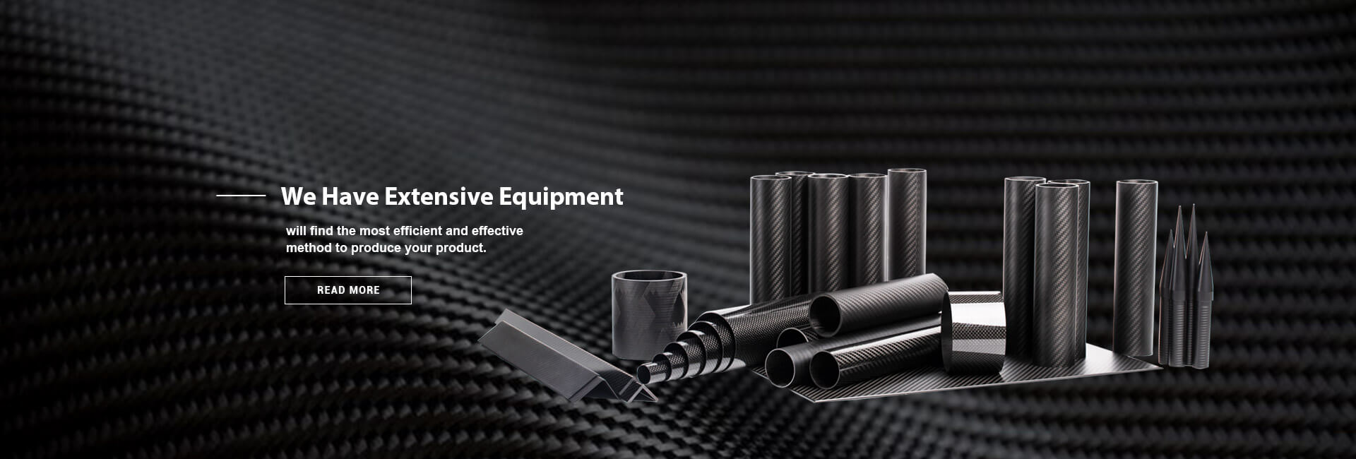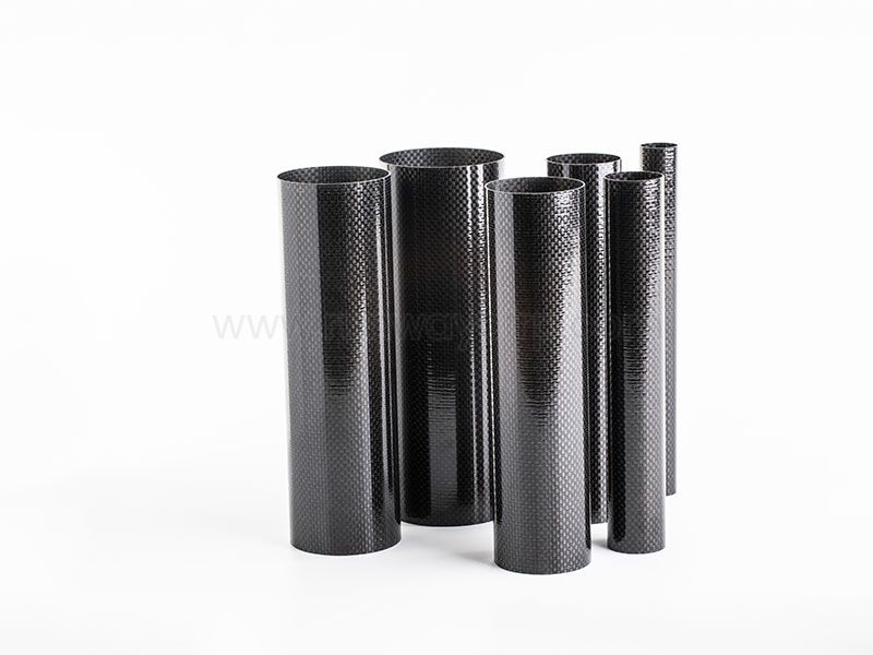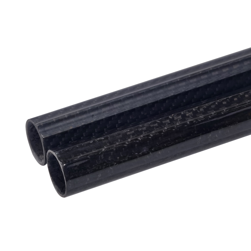
Fiber orientation controls directional strength and stiffness in a Carbon Fiber Tube. 0° fibers favor axial tension and bending, 90° fibers improve hoop stability and resistance to crushing or internal pressure, while ±45° fibers improve shear and torsional performance. Practical tubes usually combine these orientations so the laminate matches the applied load rather than relying on one fiber angle.
When I evaluate a Carbon Fiber Tube, I do not treat carbon fiber as an isotropic material like steel or aluminum. Its strength and stiffness depend on the direction of the continuous fibers, the percentage of fibers at each angle, the resin system, the stacking sequence, and the way the tube is loaded. This is why two tubes with identical outside dimensions and wall thickness can show very different structural performance.
Runway manufactures composite tubes and structural components using processes that include filament winding, roll wrapping, and pultrusion. These processes place fibers differently and therefore influence the achievable laminate architecture, dimensional control, production volume, and suitability for custom tube designs. In this guide, I explain how fiber orientation affects carbon fiber tube strength and stiffness, then connect the theory to load selection, buckling, joints, testing, and practical laminate design.
A carbon fiber tube carries load most efficiently when its fibers are aligned with the primary stress direction. Under axial tension, the fibers parallel to the tube axis carry most of the load. Under torsion, the stress field becomes shear-dominant, so fibers arranged near ±45° provide a more direct load path. Under internal pressure, hoop stresses require substantial reinforcement around the circumference, which is normally provided by fibers close to 90°.
The tube wall is therefore an engineered laminate rather than a single homogeneous material. The matrix transfers stress between adjacent plies, protects the fibers, and contributes to transverse properties, but the continuous fibers determine much of the directional stiffness and tensile capacity. If the orientation does not match the load, the resin and fiber-matrix interface may experience excessive shear, cracking, delamination, or local instability before the fibers reach their nominal tensile strength.
| Fiber orientation | Primary structural role | Typical load contribution | Main design concern |
|---|---|---|---|
| 0° | Axial strength and longitudinal stiffness | Tension, compression, bending along the tube axis | Local buckling and poor hoop support if used alone |
| 90° | Hoop strength, diameter control, and crushing resistance | Pressure, ovalization, radial compression, dimensional stability | Adds limited axial efficiency |
| +45° / -45° | Shear and torsional strength | Torsion, transverse shear, load transfer, impact tolerance | Lower axial stiffness than equivalent 0° content |
| Balanced combination | Multidirectional structural behavior | Combined axial, bending, torsional, and pressure loads | Increased design and manufacturing complexity |
0° fibers are the primary reinforcement for axial loading. In a tube used as a tie rod, boom, shaft, or lightweight column, increasing the 0° percentage generally increases longitudinal tensile stiffness and strength. However, a tube made almost entirely from 0° plies may have weak resistance to splitting, crushing, pressure, and torsional shear.
90° fibers run around the circumference of the tube. They help maintain circularity, resist hoop stress, reduce local ovalization, and distribute radial compression from clamps or fittings. For pressure vessels, fluid conduits, and tubes exposed to concentrated bearing loads, 90° reinforcement can prevent failure modes that would not be predicted from axial tensile strength alone.
±45° fibers are essential when the tube experiences torsion, transverse shear, or complex joint loading. A balanced ±45° arrangement places opposing shear directions into the laminate and reduces coupling effects. These plies can also improve damage tolerance around bonded joints, holes, clamps, and mechanical interfaces, although they usually add less axial stiffness per unit thickness than 0° plies.
The strongest fiber orientation depends on the load case. For a straight axial tensile load, 0° fibers are usually the most efficient because they align with the applied force. For torsion, a ±45° layup is more effective because the tube wall carries shear stress around the circumference and along the length. For internal pressure, 90° reinforcement becomes important because the hoop stress can exceed the longitudinal stress depending on the geometry and pressure condition.
In bending, the answer requires more care. Bending creates tension on one side of the tube and compression on the opposite side, with the largest normal stresses near the outer surfaces. Longitudinal 0° plies placed near the outside of the laminate can contribute strongly to bending stiffness, but the tube must also resist local buckling, ovalization, and transverse cracking. A balanced laminate that combines 0°, ±45°, and 90° plies is often more reliable than a nominally strong 0°-dominated design.
Compression is not simply the reverse of tension for a carbon fiber tube. The fibers may have high compressive capability, but the tube can fail through microbuckling, kink-band formation, local wall instability, end crushing, or global Euler buckling. I therefore evaluate compressive tube performance using both material allowables and structural stability calculations, particularly when the tube is long, thin-walled, or connected through a small end fitting.
I start carbon fiber tube layup design by identifying the dominant load, the load direction, the support conditions, and the likely failure mode. The table below provides an initial decision guide, but it should not replace laminate analysis or physical validation.
| Load case | Recommended orientation emphasis | Secondary orientation needs | Main verification concern |
|---|---|---|---|
| Axial tension | High 0° content | ±45° for load transfer; 90° for shape retention | Fiber tensile failure and joint transfer |
| Axial compression | 0° content with stable tube geometry | 90° for ovalization control; ±45° for damage resistance | Microbuckling and global buckling |
| Bending | 0° plies near outer surfaces | ±45° and 90° to control shear and ovalization | Local skin buckling and compression failure |
| Torsion | Balanced ±45° plies | 0° for axial coupling; 90° for dimensional stability | Interlaminar shear and torsional buckling |
| Internal pressure | High 90° content | 0° for longitudinal pressure stress; ±45° for combined loads | Hoop rupture, leakage, and fatigue |
| Radial crushing | 90° reinforcement | ±45° around fittings and contact zones | Local ovalization and wall collapse |
| Combined loading | Balanced, symmetric laminate | Orientation proportions based on load spectrum | Interaction failure and delamination |
For a primarily axial tube, I might begin with a 0°-dominated laminate and add ±45° plies near the outside or around the joints. For a drive shaft or robotic arm exposed to torque, I would give greater attention to balanced ±45° reinforcement and torsional buckling. For a pressure tube, I would prioritize hoop capacity and then check whether the axial and shear components require additional 0° and ±45° plies.
The correct design is rarely determined by fiber angle alone. Wall thickness, tube diameter, unsupported length, end constraints, material modulus, ply placement, and manufacturing tolerance all influence the final result. A thin tube with a strong laminate can still buckle, while a thicker tube with a poorly oriented laminate can fail through local cracking or excessive deformation.
Carbon fiber tube laminate layup design involves more than selecting percentages such as 60% 0°, 20% ±45°, and 20% 90°. I also examine the stacking sequence, symmetry about the mid-plane, balance between positive and negative angles, ply drops, transitions, and the location of critical plies. The same nominal fiber-angle percentages can produce different tube-level behavior when the order of the plies changes.
A balanced laminate contains comparable +45° and -45° reinforcement, which helps reduce extension-shear and bending-twist coupling. A symmetric laminate places plies in a mirrored sequence around the mid-plane, reducing residual deformation caused by extension-bending coupling. These details become increasingly important in precision tubes, long structures, rotating shafts, and components that must maintain alignment under load.
Ply placement also affects damage tolerance. Placing all 0° plies together may maximize axial efficiency, but it can create a concentrated crack path if the laminate is damaged. Interspersing ±45° and 90° plies can improve load redistribution and resistance to splitting. On the other hand, excessive orientation changes may increase manufacturing time, resin-rich regions, and the possibility of wrinkles or fiber waviness.
Manufacturing method must be considered at the same time as laminate design. Filament winding can place continuous fibers at controlled helical and hoop angles, while pultrusion is well suited to constant profiles with strong longitudinal reinforcement. Roll wrapping can support more flexible stacking sequences and tailored tube walls. Runway provides these manufacturing approaches for different composite shapes, so I would match the process to the required geometry, volume, tolerance, and orientation pattern rather than selecting a process only by unit cost.
Fiber orientation affects more than simple tensile and compressive strength. A tube can fail because it buckles globally, wrinkles locally, changes from circular to oval under bending, crushes under a fitting, or transfers load poorly into an adhesive joint. These tube-level failures can occur even when individual coupons show acceptable tensile properties.
For slender tubes, global buckling depends strongly on axial stiffness, unsupported length, end conditions, and straightness. Increasing 0° content can raise axial modulus, but it does not automatically prevent local wall buckling. Circumferential 90° reinforcement helps preserve cross-sectional shape, while ±45° plies can contribute to shear stability and resistance to deformation near supports.
Ovalization is especially important in bending and torsion. As a circular tube distorts, its bending and torsional stiffness can decrease, producing a form of structural softening. A laminate with sufficient 90° reinforcement can control this effect, while a laminate dominated by axial fibers may show good longitudinal stiffness but weaker shape retention.
Joints require separate analysis because the load path changes abruptly. Bolted connections introduce bearing and bypass loads, bonded joints create interfacial shear and peel stresses, and telescoping sections may generate radial compression and friction. I usually increase local 90° and ±45° reinforcement around fittings, then verify the design through joint coupons or representative subcomponents instead of relying only on straight-tube data.
Fiber orientation and wall thickness solve different problems. Increasing wall thickness adds material and can improve stiffness, strength, crushing resistance, and buckling resistance, but it also increases mass and may not correct a fundamentally misaligned load path. Changing orientation can improve efficiency without adding as much material, but it may introduce more manufacturing steps or reduce performance in another direction.
For example, adding 0° plies may increase axial stiffness efficiently, but those plies may contribute little to hoop strength or radial crushing. Adding 90° plies may improve pressure performance and dimensional stability, yet provide limited improvement in axial tension. A useful design compares both options using mass, deflection, failure mode, manufacturing tolerance, and service life.
I use laminate analysis to determine whether the problem is insufficient material, insufficient directional reinforcement, or inadequate stability. The final choice may involve a thicker balanced laminate, a thinner orientation-optimized laminate, or a local reinforcement scheme around joints and load introduction points. In many cases, the best solution is not the lightest theoretical laminate but the design with the lowest combined risk of manufacturing defects, damage, and field failure.
I recommend a staged verification plan before approving a production tube. First, define the laminate specification, including fiber type, resin system, nominal angles, ply areal weight, stacking sequence, cured thickness, and allowable fiber-angle tolerance. Then use classical laminate theory or finite element analysis to calculate axial, bending, torsional, pressure, and combined-load responses.
FEA should include the tube geometry, end constraints, contact areas, joints, openings, and expected load introduction method. For thin-walled tubes, I check both material failure indices and stability modes such as local buckling, global buckling, ovalization, and torsional instability. I also include realistic imperfections where possible, because perfectly straight and perfectly uniform models can overestimate tube load capacity.
Coupon testing provides material and laminate-level data. Useful tests include 0° tensile and compression, ±45° shear, short-beam interlaminar strength, open-hole tension or compression, and bonded or bolted joint testing. The final design should then be checked through full-tube testing under the actual load combination, including proof loading, stiffness measurement, cyclic loading, impact or crush testing where relevant, and inspection for delamination or permanent deformation.
Manufacturing inspection is part of structural verification. I check cured dimensions, wall thickness, fiber angle, resin-rich areas, voids, wrinkles, surface damage, and joint fit. A nominal 45° angle may not perform as intended if the fibers shift during winding, wrapping, consolidation, or machining. For critical components, dimensional inspection and non-destructive testing should be tied to defined acceptance limits rather than visual judgment alone.
A 0°-rich laminate generally favors axial stiffness, tensile efficiency, and bending performance along the tube length. Its disadvantages may include lower torsional stiffness, lower pressure capacity, greater sensitivity to splitting, and weaker resistance to radial crushing. This arrangement suits axial members only when the support and load introduction conditions are well controlled.
A ±45°-rich laminate improves torsional and shear performance and may distribute load more effectively through joints. However, it may produce lower axial stiffness than an equivalent-mass 0° laminate and can increase sensitivity to angle accuracy and interlaminar shear. It is a suitable direction for shafts, torque arms, and tubes with significant off-axis loading, but it should not be selected solely because torsion is present.
A 90°-rich laminate improves hoop stability, pressure resistance, and crushing performance. Too much 90° reinforcement can add mass without providing the axial stiffness required for bending or compression. I therefore treat the laminate as a controlled balance between directional efficiency, damage tolerance, manufacturability, and the expected load spectrum.
How Fiber Orientation Affects the Strength and Stiffness of Carbon Fiber Tubes depends on how closely the laminate matches the actual load path. I use 0° fibers for axial tension, compression, and longitudinal bending; 90° fibers for hoop stress, pressure, crushing, and dimensional stability; and balanced ±45° fibers for torsion, shear, and complex load transfer. Most practical tubes require a combination rather than a single orientation.
The next step is to document the load cases, determine the required stiffness and strength, select a preliminary stacking sequence, and compare orientation changes against wall-thickness changes. I then verify the laminate with analysis, coupon testing, joint testing, and full-tube testing that represents the real supports and load introduction points. For custom Carbon Fiber Tube projects, Runway’s filament winding, roll-wrapping, and pultrusion capabilities provide different manufacturing routes for producing tubes with controlled directional reinforcement.
+86 156 9543 6852
Science & Technology Industrial Park, Zhangdian, Zibo, Shangdong, China