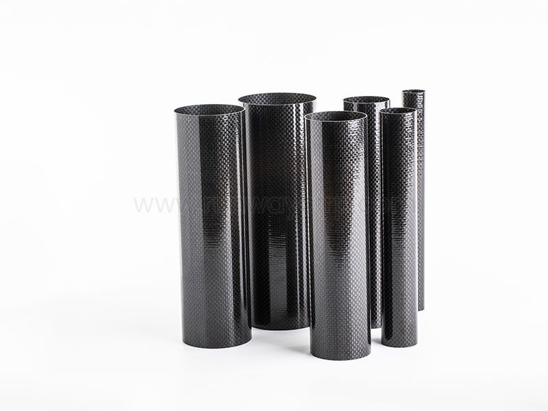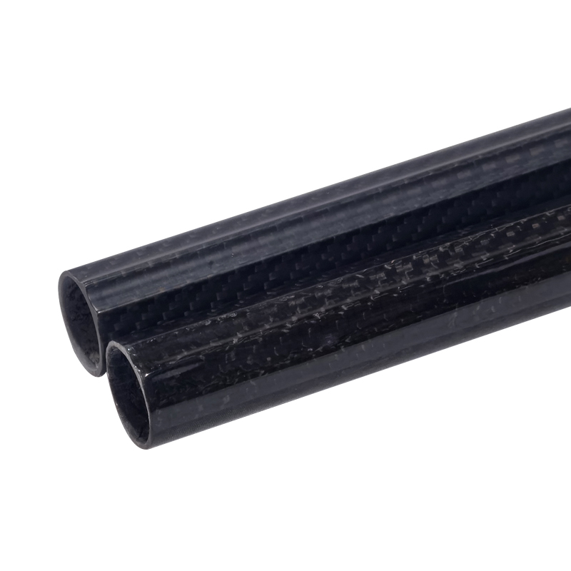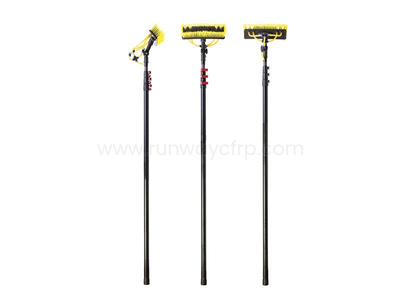
The correct Carbon Fiber Tube size depends on load type, unsupported length, stiffness targets, connection details, available clearance, environmental exposure, and required safety factor. I select the diameter first for stiffness and buckling performance, then determine wall thickness and laminate orientation for strength, local damage resistance, and manufacturing limits.
Define axial, bending, torsional, impact, vibration, and combined loads.
Set outer-diameter, inner-diameter, length, clearance, and connection constraints.
Choose a diameter that meets stiffness, buckling, and packaging requirements.
Calculate wall thickness from stress, deflection, crushing, and manufacturing limits.
Select the fiber layup and process, such as pultrusion or roll wrapping.
Validate joints, environment, tolerances, prototypes, and acceptance criteria before production.
When I prepare a carbon fiber tube sizing guide for industrial use, I begin with the complete load case rather than selecting a tube from an outer-diameter chart. The diameter controls the second moment of area, bending stiffness, buckling behavior, and available internal space. Wall thickness affects cross-sectional area, local stability, crushing resistance, connection strength, and total mass.
A tube that carries a 2,000 N axial load may require a different design from one supporting a 200 N sensor while spanning 2 m under vibration. The same nominal diameter can perform differently when produced with a unidirectional pultruded layup, a multidirectional roll-wrapped laminate, or a filament-wound structure. For this reason, I treat diameter, wall thickness, fiber orientation, manufacturing process, and end fittings as one engineering system.
Before selecting a carbon fiber tube, I record the following information:
Maximum loads: axial tension, axial compression, bending moment, torque, shear, impact, and cyclic loading.
Support condition: fixed-fixed, fixed-free, pinned, clamped, or supported through mechanical fittings.
Unsupported length: the distance between effective supports has a major effect on deflection and buckling.
Packaging limits: maximum outer diameter, minimum inner diameter, clearance around cables, shafts, bearings, and fasteners.
Operating environment: temperature, moisture, chemicals, ultraviolet exposure, abrasion, and electrical requirements.
Service life: static, intermittent, fatigue, vibration, or repeated impact operation.
Safety factor: the selected value must reflect uncertainty in loads, material data, joints, fatigue, and failure consequences.
The practical specification should also include dimensional tolerances, surface finish, cut length, hole locations, end squareness, resin system, fiber grade, laminate schedule, and inspection requirements. Without these details, a supplier may quote a nominal tube that fits dimensionally but does not satisfy the actual structural requirement.
The wall thickness still matters because a thin wall may be vulnerable to local crushing, ovalization, delamination, impact damage, and instability around holes or fittings. A larger diameter with an excessively thin wall can provide strong global bending stiffness but poor local load transfer. A smaller tube with a thick wall may resist local damage but require more material and produce lower bending stiffness for the same mass.
| Geometry change | Primary effect | Typical design reason |
|---|---|---|
| Increase outer diameter | Raises bending stiffness and column stability | Long spans, beams, robotic arms, lightweight frames |
| Increase inner diameter | Adds clearance and reduces mass if outer diameter remains fixed | Shafts, cables, fluid lines, telescoping sections |
| Increase wall thickness | Raises area, local crushing resistance, and connection capacity | Compression, bearing loads, threaded inserts, impact |
| Reduce unsupported length | Reduces deflection and buckling risk | Add supports, bearings, guides, or cross-bracing |
| Add ±45° material | Improves torsional and in-plane shear response | Drive shafts, articulated arms, torque members |
| Add 90° or hoop material | Improves transverse stability and pressure resistance | Filament-wound or pressure-loaded tubes |
I generally choose a larger diameter when bending stiffness, long-span deflection, or column buckling controls the design and the surrounding equipment allows the added envelope. I choose a thicker wall when local crushing, fastener bearing, impact, handling damage, or limited outer clearance controls the design.
For example, consider an illustrative tube with a 40 mm outer diameter and a 2 mm wall. Its inner diameter is 36 mm. If the outer diameter increases to 50 mm while the wall remains 2 mm, the section gains a substantial increase in bending stiffness because of the fourth-power relationship in (I). If the 40 mm tube instead increases from 2 mm to 4 mm wall thickness, its area and local resistance improve, but the increase in bending stiffness is usually less efficient per added mass than increasing diameter.
This comparison changes when internal clearance is fixed. If a 36 mm passage is required for a shaft or cable bundle, increasing the wall from 2 mm to 4 mm may be the only practical option. Packaging, fittings, telescoping overlap, bearing seats, and access for inspection must be evaluated before choosing the geometry.
I use the following engineering workflow to calculate a preliminary size:
I list maximum static loads, transient loads, fatigue cycles, impact energy, torque, bending moments, and support reactions. I then identify whether the tube behaves as a beam, column, shaft, pressure member, guide, enclosure, or combined structural component.
I define the maximum outer diameter, minimum inner diameter, total length, unsupported span, end overlap, fitting envelope, and required access. I also identify whether the tube must fit inside another tube or telescope over a mating section.
I select a preliminary outer diameter based on bending stiffness, buckling resistance, natural frequency, clearance, and available connection space. For long slender tubes, I avoid selecting diameter only from axial strength because deflection and stability often govern earlier.
I calculate the required cross-sectional area for axial loads and the required (I) for bending. I then increase wall thickness as needed for local crushing, hole strength, insert installation, impact, torsional shear, and manufacturing tolerances.
A typical structural laminate may combine 0° fibers for axial and bending loads, ±45° fibers for torsion and shear, and 90° or hoop fibers for transverse stability. The exact percentages must be determined from verified material properties, laminate analysis, and the production process.
I check tensile rupture, compression failure, global buckling, local buckling, ovalization, delamination, bearing failure, adhesive failure, insert pull-out, hole-edge splitting, and end damage. A tube is not adequately sized when only the nominal wall stress has been checked.
The safety factor should be selected from the design code, company practice, load uncertainty, material variation, fatigue condition, joint reliability, and consequence of failure. I do not apply one generic value to every tube because a guarded machine cover and a lifting mechanism have different risk profiles.
I request material certificates, dimensional inspection, laminate details, and test data from the supplier. I then test coupons, representative tube sections, joints, and complete prototypes under the governing load cases.
Buckling resistance depends on diameter, wall thickness, unsupported length, end restraint, laminate modulus, ovality, imperfections, and load eccentricity. A tube under compression should be checked for both global column buckling and local wall instability. Increasing diameter can improve global buckling resistance, but an overly thin wall may become sensitive to local buckling and handling damage.
Common failure modes include local crushing beneath clamps, delamination near holes or bonded joints, ovalization under bending or radial loads, and joint bearing failure around bolts or pins. End damage can begin during cutting, drilling, insertion, or transport, so tube ends should be protected, inspected, and designed with suitable sleeves or inserts.
For compression members, I prefer a design that includes load introduction details rather than treating the tube as an isolated cylinder. Bonded sleeves, internal mandrels, metal inserts, and larger bearing surfaces can reduce local stresses. The joint should be tested with the actual fastener torque, adhesive thickness, surface preparation, and loading direction.
The manufacturing method affects fiber orientation, dimensional control, cost, length capability, and suitability for different load directions.
| Process | Fiber orientation | Typical advantage | Main design limitation |
|---|---|---|---|
| Pultrusion | Mainly continuous longitudinal fibers | Efficient axial stiffness, repeatable profiles, production volume | Less flexible for complex angles and multidirectional laminates |
| Roll wrapping | Controlled 0°, ±45°, and 90° layers | Flexible laminate design and accurate custom wall construction | More processing steps and possible seam or consolidation considerations |
| Filament winding | Helical and hoop fiber paths | Efficient cylindrical structures and pressure or torsion designs | Fiber angle must match the load case |
| Braiding | Interlaced axial and angled fibers | Damage tolerance and multidirectional reinforcement | May have lower axial efficiency than a highly aligned laminate |
| Hybrid construction | Carbon, glass, or aramid combinations | Balances cost, impact response, insulation, and stiffness | Requires careful interface and process control |
Runway manufactures composite tubes and structural components using filament winding, roll wrapping, and pultrusion, and also lists complementary products such as plates, rods, shapes, connectors, and CNC machining support. That process range is relevant when a project requires different tube constructions for axial members, telescoping sections, fittings, or custom structural assemblies.
Carbon fiber tubes are often selected when low mass, high directional stiffness, corrosion resistance, or controlled thermal expansion matters. Aluminum is usually easier to machine, drill, repair, and source in standard sections, while steel provides high strength, impact tolerance, and predictable isotropic behavior at a higher mass.
The correct comparison should use equal structural function rather than equal outside diameter. I compare mass at the required stiffness, deflection under load, fatigue life, corrosion exposure, joining method, inspection cost, and replacement procedure. Carbon fiber may reduce mass while requiring more careful joint design and damage inspection than an aluminum or steel tube.
Carbon fiber tubes are commonly considered for robotic arms, inspection poles, automation frames, camera supports, machine components, lightweight shafts, telescoping structures, and corrosion-exposed equipment. They are less attractive when the application involves severe uncontrolled impact, frequent field drilling, high-temperature exposure beyond the resin system, or very low-volume production without a clear mass or performance requirement.
Before requesting a quotation, I prepare a written specification containing:
Outer diameter and inner diameter, including tolerance limits.
Wall thickness or laminate thickness range.
Cut length, straightness, roundness, and end squareness.
Required fiber orientation and resin system.
Axial, bending, torsional, impact, and fatigue load cases.
Unsupported span, support conditions, and joint configuration.
Operating temperature, moisture, chemicals, ultraviolet exposure, and abrasion.
Surface finish, color, electrical conductivity, and insulation requirements.
Hole, insert, sleeve, adhesive, and end-fitting details.
Inspection records, test coupons, prototype quantity, and acceptance criteria.
For prototype validation, I test the tube in the same support and joint conditions used in the machine. I measure deflection, strain, permanent deformation, vibration response, and failure location rather than recording only the ultimate load. If a test fails, I classify the failure as material rupture, delamination, local crushing, buckling, joint failure, adhesive failure, or manufacturing defect before changing the geometry.
To How to Choose the Right Carbon Fiber Tube Diameter and Wall Thickness for Industrial Applications, I recommend starting with loads, span, support conditions, packaging, and connection details rather than a standard tube catalog. Select diameter primarily for bending stiffness, deflection, natural frequency, and buckling resistance, then select wall thickness for axial capacity, torsion, local stability, impact resistance, and joint load transfer.
A larger diameter is usually more efficient for long-span bending and column stability, while a thicker wall is more useful when internal clearance is fixed or local crushing and fastener loads control the design. The final carbon fiber tube specification should identify the laminate, process, tolerances, fittings, environment, safety factor, and validation tests.
For industrial procurement, I would send the supplier a complete RFQ package, request process-specific recommendations, review material and dimensional data, test representative joints, and approve production only after the prototype meets the defined load, stiffness, buckling, vibration, and acceptance criteria.
+86 156 9543 6852
Science & Technology Industrial Park, Zhangdian, Zibo, Shangdong, China