When I evaluate what makes molded carbon fiber parts so special, I focus on how their fiber reinforcement, resin matrix, heat, pressure, and tooling work together. Unlike a loose carbon-fiber sheet, a molded component is formed into a defined geometry with controlled fiber orientation, wall thickness, surface finish, and load-bearing behavior. This allows manufacturers to produce lightweight parts with high stiffness, corrosion resistance, dimensional stability, and repeatable performance.
!
Molded carbon fiber parts are used when reducing mass alone is not enough. Engineers also need predictable strength, controlled deflection, resistance to chemicals or moisture, and a shape that would be difficult to manufacture from aluminum, steel, or traditional machined materials. In this guide, I explain how carbon fiber molding works, how to select a suitable process, what design details affect cost and quality, and where molded carbon fiber components provide the greatest practical value.
Molded carbon fiber parts are composite components made by placing carbon-fiber reinforcement inside a mold, combining it with a polymer resin, and consolidating the structure with controlled heat, pressure, vacuum, or a combination of these methods. The carbon fibers carry much of the tensile load, while the resin binds the fibers together, transfers stress, protects the reinforcement, and fixes the final shape.
The finished performance depends on more than the carbon fiber grade. Fiber direction, laminate sequence, resin chemistry, fiber volume, cure temperature, pressure level, void content, and dimensional control all influence the final part. A properly designed component can place fibers along the primary load paths instead of distributing material equally in every direction.
Molded carbon fiber components may use thermoset systems, such as epoxy or vinyl ester, or thermoplastic systems, such as PEEK, PPS, or nylon. Thermoset parts generally require a chemical curing cycle, while thermoplastic parts are softened with heat and consolidated under pressure. The correct material depends on temperature exposure, impact requirements, production volume, joining method, and end-of-life considerations.
The main reason is the combination of low density and directional mechanical performance. Carbon fiber has a high strength-to-weight ratio, meaning an engineer can often reduce mass while maintaining the required load capacity. The benefit is especially significant in moving structures, aircraft systems, robotic arms, vehicle components, sporting equipment, and long-span structures.
Carbon fiber is also stiff in the direction of reinforcement. By arranging unidirectional plies, woven fabric, braided fibers, or chopped fibers according to the expected loads, I can tune stiffness in selected directions. This is different from isotropic metals, where strength and stiffness are more uniform in every direction but may require additional mass to meet a directional performance target.
Corrosion resistance is another important benefit. Carbon fiber itself does not rust, and the resin matrix protects the reinforcement from many environmental exposures. However, engineers must still assess ultraviolet radiation, moisture absorption, chemical compatibility, galvanic corrosion when carbon contacts aluminum, and temperature cycling before approving a design.
Design flexibility also contributes to the value of molded parts. A single molded component can combine ribs, flanges, curved surfaces, mounting points, and aerodynamic contours that would otherwise require several machined or assembled pieces. This can reduce fasteners and secondary assembly operations, although complex geometry usually increases tooling and inspection requirements.
Carbon fiber molding processes vary according to production quantity, part geometry, structural requirements, tolerance, surface finish, and tooling budget. The following sequence describes the main stages I review when assessing carbon fibre parts manufacturing.
Design the mold and laminate. Engineers define the part geometry, mold split lines, draft angles, fiber orientation, ply schedule, inserts, tolerances, and cure strategy. The mold must support the intended pressure and temperature while maintaining stable dimensions.
Prepare the mold surface. The tool is cleaned, inspected, and treated with a suitable release system. The surface condition affects demolding, appearance, dimensional accuracy, and the risk of resin sticking to the tool.
Place and orient the reinforcement. Prepreg, dry fabric, braided reinforcement, or chopped carbon fiber is positioned according to the laminate design. Orientation may include 0°, 90°, and ±45° plies, depending on tensile, bending, torsional, and shear loads.
Introduce the resin. In prepreg molding, resin is already distributed through the reinforcement. In resin transfer molding, resin is injected into a dry-fiber preform. In compression molding, a charged material is placed into a heated mold and compressed into shape.
Remove trapped air. Vacuum pressure, debulking, venting, and controlled resin flow help reduce voids and porosity. Poor air removal can lower interlaminar strength and create visible surface defects.
Apply heat or pressure. Autoclaves, heated presses, compression molds, ovens, or matched metal tools consolidate the material. Temperature and pressure must follow the resin supplier’s cure window rather than relying on a general cycle.
Cure the part. The resin cross-links in a thermoset system or consolidates in a thermoplastic system. Time, temperature ramp rate, dwell period, pressure, and cooling rate affect residual stress and dimensional stability.
Demold and finish the component. After cooling, the part is removed, trimmed, drilled, machined, bonded, or fitted with inserts as required. Cutting tools and parameters must limit delamination, fiber pullout, and heat damage.
Inspect the finished part. Inspection may include visual checks, dimensional measurement, ultrasonic testing, tap testing, radiography, weight verification, and mechanical validation. The selected method should correspond to the part’s safety level and structural function.
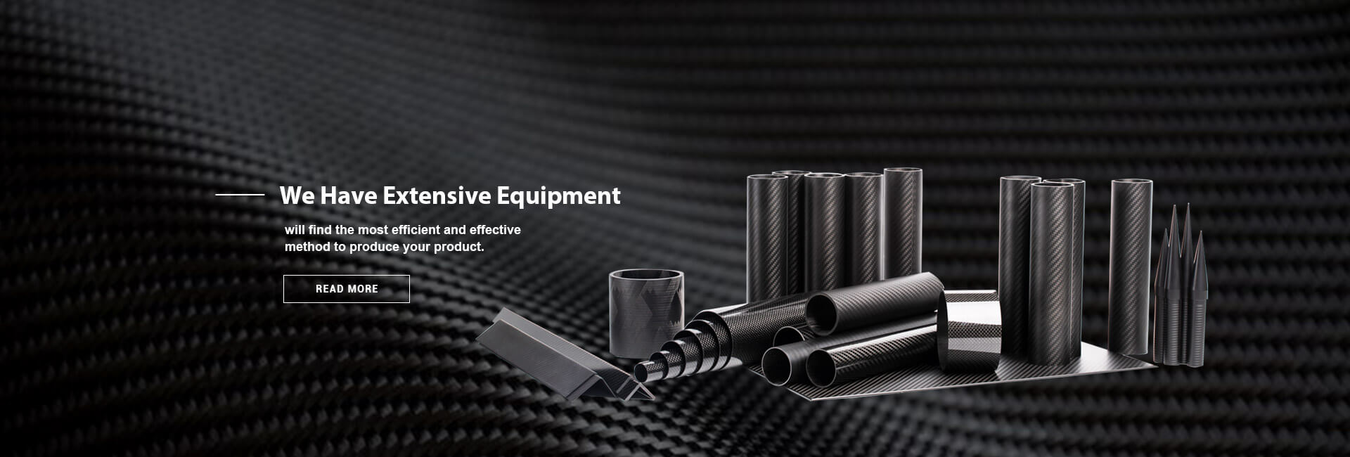
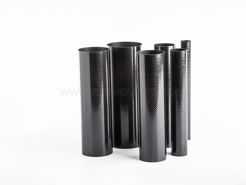
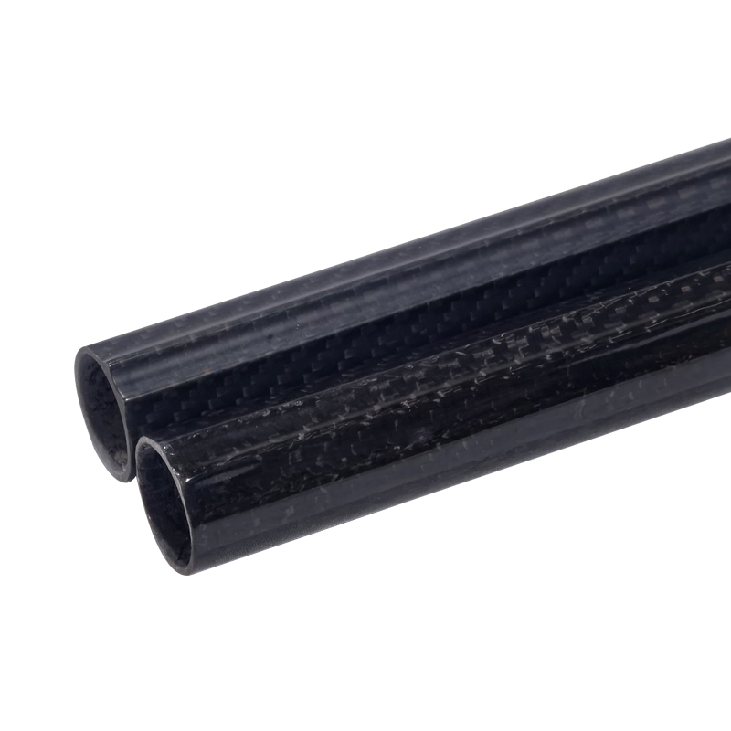
Common manufacturing routes include compression molding, autoclave molding, resin transfer molding, vacuum infusion, pultrusion, filament winding, and press molding of sheet molding compound. Runway produces carbon-fiber-reinforced shapes and structural components through techniques including filament winding, roll wrapping, and pultrusion, with product categories covering tubes, plates, poles, rods, angles, and related composite components.
No single molding process is suitable for every project. I recommend comparing the following variables before requesting a quotation or approving tooling.
| Requirement | More suitable process direction |
|---|---|
| Low production volume and complex structural laminate | Prepreg with autoclave or controlled oven curing |
| Medium-volume parts with enclosed geometry | Resin transfer molding |
| High-volume parts with repeatable shapes | Compression molding |
| Long constant cross-sections | Pultrusion |
| Tubes, shafts, and circular structures | Filament winding |
| Large surfaces with moderate pressure requirements | Vacuum infusion |
| Fast-cycle thermoplastic production | Heated press or compression molding |
| Premium cosmetic surfaces | Matched tooling with controlled mold-side finish |
Production volume strongly affects the tooling decision. A high-cost precision mold may be justified for thousands of parts, while a lower-cost tool or bladder-based method may be more appropriate for prototypes and small batches. Geometry also matters because deep draws, sharp transitions, internal ribs, and undercuts can increase the number of tool sections and secondary operations.
Tolerance requirements should be defined before process selection. If a part requires tight hole positions, controlled flatness, or consistent wall thickness, the manufacturer may need matched tooling, post-cure machining, or a dedicated inspection fixture. Surface finish should also be classified as cosmetic, functional, or non-visible because each level affects tool polish, mold maintenance, and acceptance criteria.
Draft angles help the cured part leave the mold without excessive force. The required angle depends on tool material, surface texture, release system, depth, and geometry, but designers should avoid assuming that every vertical wall can be molded without draft. A release analysis during the design stage can prevent tool damage and unexpected split lines.
Wall thickness should be selected for load requirements, process stability, and heat transfer. Very thin sections may create incomplete consolidation, bridging, or local distortion, while abrupt thickness changes can produce resin-rich areas and residual stress. I prefer gradual transitions, tapered edges, and local reinforcement rather than sudden changes in section thickness.
Radii are essential at corners. Tight internal corners can prevent reinforcement from conforming to the mold, leading to bridging, wrinkles, voids, and fiber misalignment. Larger radii generally improve drape and reduce stress concentration, especially when woven fabric or multiple directional plies are required.
Fiber orientation should follow the actual load path. Zero-degree fibers normally support axial loads, ±45-degree fibers support shear and torsion, and 90-degree fibers support transverse loads and dimensional stability. A balanced laminate may be preferable when loading is uncertain, but adding material in every direction can increase cost and mass.
Inserts require careful load transfer design. Metallic inserts should be compatible with the resin, protected from galvanic interaction, and supported by adequate laminate thickness. Bonded or co-cured inserts may reduce assembly time, but they also introduce inspection and repair considerations.
Undercuts can be molded using collapsible cores, removable inserts, bladders, or multi-part tooling. Each solution adds cost and may affect cycle time. Before finalizing the geometry, I would confirm how the tool opens, how the part is removed, where flash can occur, and how every internal surface will be inspected.
The most common molded carbon fiber defects include voids, porosity, delamination, resin-rich zones, dry spots, wrinkles, fiber misalignment, bridging, surface pinholes, dimensional distortion, and insert movement. These defects do not all have the same effect, so acceptance criteria should distinguish between cosmetic imperfections and structural discontinuities.
Voids and porosity reduce the effective load-bearing area and may accelerate moisture penetration. Delamination separates laminate layers and can reduce resistance to impact, bending, and interlaminar shear. Fiber misalignment is particularly important because a small orientation error can reduce performance along the intended load direction.
Inspection should combine several methods rather than relying on visual examination alone. Dimensional inspection can use coordinate measuring machines, optical scanners, gauges, or dedicated fixtures. Ultrasonic testing can identify internal discontinuities, while weight checks can reveal resin-content variation when used with process records and defined limits.
A practical quality plan should identify the inspection frequency, sampling level, allowable defect size, traceability requirements, cure records, material certificates, and corrective-action procedure. For safety-critical applications, mechanical coupons or representative validation parts may be required. The inspection method should be matched to the consequences of failure rather than selected only for convenience.
Repairability differs from metal repair. Small surface damage may be sanded and overlaid with a bonded patch, but deeper damage requires engineering assessment, controlled scarf preparation, compatible resin, and post-repair inspection. A repair that restores appearance may not restore the original strength, so repair procedures should define structural acceptance criteria.
Recyclability is another lifecycle consideration. Thermoset carbon fiber parts are difficult to remelt because the cured resin cannot be reheated into its original liquid state. Mechanical recycling, pyrolysis, and solvolysis can recover fibers, but recovered fiber may have reduced length, altered sizing, or lower structural value. Thermoplastic carbon fiber parts can offer easier reshaping and welding, although their processing temperature and material cost may be higher.
Environmental tradeoffs should be considered across the entire product life. A molded carbon fiber component may reduce operating energy in vehicles, aircraft, equipment, or moving structures because of its lower mass. However, energy-intensive fiber production, resin chemistry, tooling, scrap, and end-of-life treatment must be included in a complete assessment.
In automotive applications, molded carbon fiber parts can serve as structural brackets, body panels, suspension components, battery enclosures, aerodynamic elements, and interior frames. The strongest business case usually appears where mass reduction affects acceleration, range, handling, or payload capacity. Designers must still account for crash energy management, impact damage, joining, fire performance, and repair procedures.
Aerospace applications include access panels, seat structures, fairings, ducts, control surfaces, interior components, and secondary support structures. Aerospace parts commonly require strict traceability, controlled cure records, non-destructive inspection, flammability evaluation, and documented material systems. The cost of qualification can be significant, so the design should remain stable before production tooling begins.
Sports equipment uses molded carbon fiber in bicycle frames, helmets, racquets, paddles, skis, prosthetic components, and protective structures. The value comes from controlled stiffness, low mass, vibration response, and customized geometry. Impact behavior is particularly important because a lightweight part can still experience severe local damage from falls or concentrated impacts.
Marine components benefit from corrosion resistance and low mass. Applications include masts, booms, panels, supports, hatch structures, instrument mounts, and underwater equipment. Designers must evaluate water absorption, ultraviolet exposure, impact, coating adhesion, and galvanic isolation from aluminum fittings.
Medical products may use carbon fiber in imaging tables, positioning supports, prosthetic structures, and radiolucent components. These parts require careful control of cleanliness, biocompatibility where applicable, dimensional stability, and compatibility with imaging or sterilization environments.
Renewable-energy systems use carbon fiber in lightweight blades, robotic inspection equipment, structural supports, and access components. Construction and infrastructure applications include strengthening plates, bridge elements, reinforcement bars, monitoring structures, and corrosion-resistant supports. Consumer products may include camera equipment, outdoor tools, luggage frames, furniture, and precision housings.
I recommend custom molded carbon fiber components when the standard tube, plate, or pultruded profile cannot meet the required geometry or load path. Custom molding is particularly appropriate when a part must combine curved surfaces, integrated ribs, mounting features, variable thickness, or a specific fiber orientation. It can also reduce assembly when several pieces can be consolidated into one molded structure.
For small manufacturers, the most important question is whether the expected performance justifies tooling and engineering costs. A prototype may be produced with flexible tooling, hand layup, vacuum bagging, or a simpler compression mold before committing to a production tool. This staged approach reduces the risk of paying for a complex mold before the design has been validated.
When comparing suppliers, I would request evidence of process capability, material traceability, inspection equipment, sample parts, dimensional reports, and experience with similar geometries. Runway’s product and manufacturing range includes carbon fiber tubes, plates, pultruded products, filament-wound tubes, telescopic structures, and CNC machining support. For a custom project, the supplier should still confirm the exact reinforcement, resin, tolerance, cure method, surface requirement, and inspection plan rather than treating all carbon fiber parts as equivalent.
Before choosing molded carbon fiber parts, I would confirm the following:
What makes molded carbon fiber parts so special is the way manufacturing control converts carbon fiber and resin into a lightweight structure with targeted strength, stiffness, corrosion resistance, durability, and geometric freedom. Their value does not come from the material name alone; it comes from matching fiber orientation, resin system, molding pressure, cure cycle, tooling, inspection, and service conditions to the engineering requirement.
When I compare molded carbon fiber parts with aluminum, steel, or traditional laminate construction, I look at the complete system rather than material price alone. A molded component may reduce mass and assembly work, but tooling, inspection, repair, and end-of-life treatment must be included in the decision. The best next step is to define the load cases, production volume, geometry, tolerance, surface finish, and lifecycle requirements before selecting compression molding, autoclave molding, resin transfer molding, pultrusion, or filament winding.
+86 156 9543 6852
Science & Technology Industrial Park, Zhangdian, Zibo, Shangdong, China