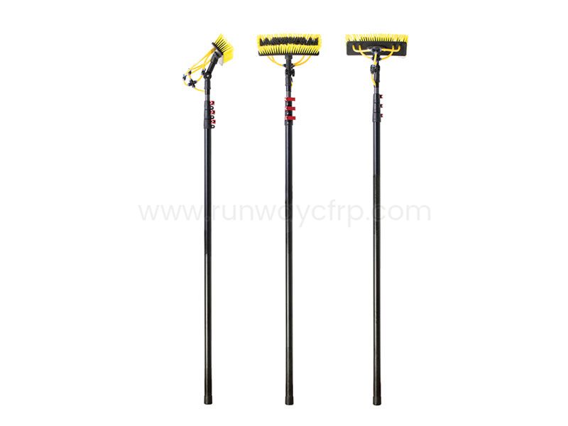
Building with carbon-fiber tube requires more than cutting hollow composite sections and joining them together. I first select the tube based on bending, torsional, axial, crushing, and joint loads, then prepare each surface, control alignment with a rigid jig, and inspect or test the completed structure before service. This method applies to lightweight frames, robotics, aerospace assemblies, inspection equipment, and small structural projects.
Carbon-fiber tube sizing must account for bending, torsion, buckling, crushing, and connection loads.
Structural epoxy works only when surfaces, bond-line thickness, alignment, and curing conditions are controlled.
Jigs, square reference surfaces, and measured diagonals reduce alignment errors before permanent bonding.
Commercial tubes usually provide better repeatability, while DIY fabrication requires tooling, process control, and testing.
Finished assemblies should be inspected for splitting, delamination, voids, poor bonds, and joint movement.
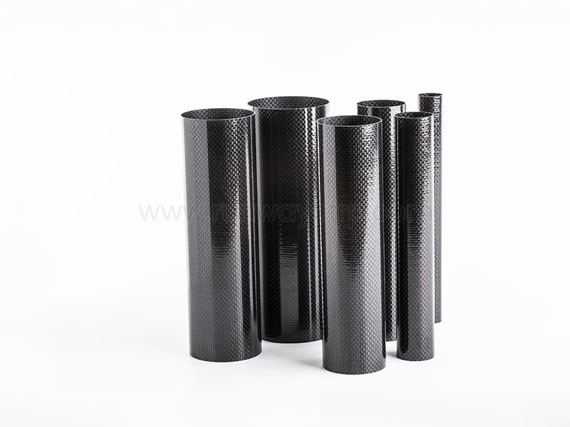
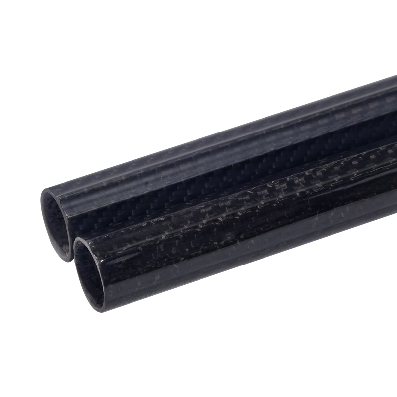
Carbon-fiber tube construction uses hollow Carbon Fiber Tube sections as beams, columns, braces, shafts, booms, or frame members. The tube consists of carbon fibers embedded in a polymer resin matrix, with fiber direction and wall thickness determining how it carries load. Unlike isotropic metals, carbon-fiber tubes are anisotropic, so strength and stiffness vary according to the orientation of the fibers.
I treat carbon-fiber tube construction as a complete structural system rather than a tube-selection exercise. The tube, adhesive, connector, fastener, joint sleeve, end reinforcement, and surrounding load path all affect the final result. A tube that performs well in a simple bending test can still fail through local crushing, splitting, delamination, or joint rotation.
Runway Composite Co., Ltd. manufactures composite tubes, rods, plates, connectors, pultruded products, and filament-wound products. Its production options include filament winding, roll wrapping, and pultrusion, allowing tube construction to be matched to different cross-sections, fiber orientations, surface requirements, and production quantities. The company also works with carbon, glass, aramid, and hybrid reinforcement systems.
Before I begin fabrication, I define the structure’s dimensions, loading conditions, operating environment, and expected service life. I record the unsupported span, support locations, concentrated loads, distributed loads, torsional forces, impact conditions, temperature range, moisture exposure, and any vibration. Without these values, selecting a tube by outside diameter alone can produce an unsafe design.
I also prepare a drawing that identifies tube lengths, joint locations, connector depths, adhesive areas, fastener positions, and reference datums. For repeated production, I include tolerances for length, hole location, squareness, connector fit, and bond-line thickness. A practical drawing should identify whether each member is loaded in tension, compression, bending, torsion, or a combination of these conditions.
Carbon-fiber tubes with documented outside diameter, inside diameter, wall thickness, length, and fiber construction
Structural epoxy selected for the expected temperature and load condition
Internal sleeves, external sleeves, bonded inserts, or purpose-built connectors
Abrasive paper, solvent compatible with the resin system, lint-free wipes, and dust extraction
Fine-tooth saw, abrasive cut-off wheel, or diamond cutting tool
Drill press or guided drill fixture for accurate holes
Square reference surface, clamps, angle blocks, measuring tape, calipers, and digital level
Spacers or shims for controlling adhesive thickness
Personal protective equipment, including gloves, eye protection, and suitable respiratory protection
I begin by separating the applied loads into axial, bending, torsional, and local joint forces. For a beam under a central point load, the maximum bending moment is commonly estimated as:
[ M_{max}=\frac{PL}{4} ]
where (P) is the applied load and (L) is the simply supported span. For a uniformly distributed load, I use the appropriate beam equation for the support condition rather than applying the point-load formula.
Next, I estimate bending stress using:
[ \sigma=\frac{Mc}{I} ]
Here, (M) is bending moment, (c) is the distance from the neutral axis to the outer wall, and (I) is the second moment of area. For a round hollow tube:
[ I=\frac{\pi}{64}(D_o^4-D_i^4) ]
where (D_o) is the outside diameter and (D_i) is the inside diameter. Because diameter appears to the fourth power, increasing tube diameter can improve bending stiffness more efficiently than adding the same mass through wall thickness, although local crushing and connector fit may favor a thicker wall.
For torsion, I calculate the applied torque and check the tube’s torsional stiffness, fiber orientation, and joint capacity. I also check compression members for buckling using the unsupported length, end conditions, elastic modulus, and second moment of area. A tube can have sufficient material strength but still buckle because the member is too slender.
I select the tube after comparing the calculated loads with allowable values that include a safety factor. I do not use a catalog tensile-strength figure as the allowable load for a finished assembly because the real structure includes holes, joints, eccentric loads, surface damage, temperature effects, and manufacturing variation.
For long beams, outside diameter strongly influences bending stiffness. For short compression members and connector regions, wall thickness becomes more important because the tube may crush or split under localized force. Pultruded, roll-wrapped, and filament-wound tubes can have different fiber distributions, so I request construction details instead of assuming that two tubes with identical dimensions will have identical behavior.
| Design issue | Primary tube feature to review |
|---|---|
| Long-span bending | Outside diameter, second moment of area, longitudinal fiber content |
| Axial compression | Wall thickness, straightness, buckling length, end restraint |
| Torsion | Off-axis fiber orientation, wall thickness, joint design |
| Connector crushing | Local wall thickness, sleeve length, bearing area |
| Repeated impact | Toughness, protective outer layer, damage tolerance |
| High-temperature service | Resin temperature capability and environmental data |
I usually prefer a larger-diameter tube for a long, lightweight beam when the surrounding geometry permits it. I use local sleeves, internal plugs, or additional wraps when loads enter through a small connector or fastener. These reinforcements should be designed around the actual load path rather than added as a general repair.
I mark the cutting plane around the entire circumference using a wraparound guide or a square fixture. I support the tube close to the cut so vibration does not create splintering or an angled end. For thin-wall tubes, I avoid clamping pressure that can ovalize the section.
A fine diamond blade or abrasive wheel can produce a clean cut when used with controlled feed pressure and dust extraction. I seal or protect the cut area after machining if the exposed laminate is likely to absorb moisture or suffer edge damage. I inspect the end for lifted plies, cracks, resin breakout, and changes in roundness.
Drilling into carbon-fiber tubing is possible, but I use a carbide or diamond-coated bit, a backing fixture, and moderate feed pressure. I avoid forcing a standard twist drill through the laminate because it can catch fibers, delaminate the wall, or enlarge the exit hole. If a bolt must pass through the tube, I reinforce the hole with an internal sleeve, bonded insert, or locally thickened laminate.
I dry-fit every joint before applying adhesive. The connector should enter to the intended depth without excessive force, and the tube should remain round enough to provide a consistent bond area. If the fit is too loose, the adhesive gap may become excessive; if it is too tight, adhesive may be squeezed out before the parts reach their final position.
I abrade the bonding areas with controlled, even strokes until the glossy surface is removed. I do not grind deeply into the carbon fibers because cutting structural fibers can reduce the tube’s local capacity. After abrasion, I remove dust with a clean method approved for the adhesive system and avoid touching the prepared surfaces with bare hands.
The best adhesive for carbon-fiber tubes depends on the resin, service temperature, gap, cure schedule, and load type. For structural work, I generally use a two-part structural epoxy with published tensile-shear, temperature, and cure data rather than a general-purpose instant adhesive. The bond line should be controlled with spacers, glass beads, machined shoulders, or connector geometry.
Carbon-fiber tube joints and connectors should transfer load over a sufficient length rather than concentrating force at one edge. Common methods include internal sleeves, external sleeves, bonded aluminum or composite inserts, machined couplers, and hybrid bonded-fastened connections. I select the method according to whether the joint carries tension, compression, bending, torsion, or cyclic loading.
For an internal sleeve, I check insertion depth, adhesive coverage, clearance, and the transition between the rigid connector and the flexible tube wall. A short sleeve may produce a high local stress concentration, while an excessively rigid connector can shift failure into the tube edge. I add tapered transitions or bonded reinforcement when the geometry creates an abrupt stiffness change.
I apply adhesive to both compatible surfaces when the manufacturer’s instructions permit it, then rotate or slide the parts together to distribute the adhesive. I remove excess adhesive without disturbing the alignment. The assembly remains clamped until the adhesive reaches its specified handling strength, followed by the full cure required for the intended load.
I use a flat reference surface, fixed stops, angle blocks, and adjustable clamps to establish the frame geometry. Before bonding, I measure the overall length, diagonals, member angles, connector insertion depths, and tube centerlines. Equal diagonals are useful for checking a rectangular frame, but I also verify each critical angle independently.
A jig should resist movement during adhesive cure, not merely position the parts during initial assembly. I place clamps where they cannot crush thin-wall tubes, and I use soft pads or shaped saddles to distribute pressure. For long members, I add intermediate supports to prevent sagging while the adhesive is still mobile.
After the adhesive has cured, I repeat the measurements and compare them with the drawing tolerances. A small alignment error at one joint can create secondary bending in every connected member. For rotating shafts, camera poles, robotic arms, and long inspection tools, I also check runout and angular deviation because these errors can produce vibration or uneven bearing loads.
I choose a joint according to the load path, inspection access, service environment, and required disassembly. A bonded sleeve offers a clean exterior and distributes force over a longer area, while a mechanical fastener allows removal but introduces holes and local bearing stress. A hybrid joint can provide assembly control and additional retention, but it requires careful isolation between dissimilar materials.
Bonded joints fail for several recurring reasons: contaminated surfaces, insufficient abrasion, poor adhesive mixing, excessive bond-line thickness, trapped air, inadequate cure, and movement during cure. I inspect the joint for visible adhesive squeeze-out, uniform seating, gaps, connector rotation, and exposed dry areas. If the joint is safety-critical, I validate a representative sample through proof loading or destructive testing.
I also consider galvanic corrosion when carbon fiber contacts aluminum or other conductive metals in a wet environment. A compatible insulating layer, primer, coating, glass-fiber isolation ply, or nonconductive sleeve may be required. Fasteners should not be tightened against an unreinforced tube wall unless the design specifically includes a bearing insert.
Carbon-fiber tubes and aluminum tubes solve different structural problems. Carbon fiber generally offers high stiffness and strength relative to mass, corrosion resistance, and directional control, while aluminum provides easier machining, predictable ductility, lower tooling complexity, and simpler field repair.
| Factor | Carbon-fiber tube | Aluminum tube |
|---|---|---|
| Mass efficiency | Often favorable for stiffness- or strength-limited designs | Usually requires more mass for equivalent stiffness |
| Fiber direction | Properties can be tailored by orientation | Properties are largely uniform by direction |
| Corrosion | Does not rust, but galvanic contact can be an issue | Can corrode under unsuitable exposure |
| Failure behavior | Can crack, split, or delaminate with limited warning | More likely to bend or yield visibly |
| Machining | Requires dust control and laminate protection | Easier with common metalworking tools |
| Joining | Requires adhesive control or reinforced fasteners | Welding, bolting, riveting, and bonding are available |
| Repair | Often requires bonded patches or replacement | Straightening, welding, or replacement may be simpler |
| Cost structure | Higher material and process-control cost | Lower entry cost for simple projects |
For a small prototype with many holes, frequent changes, and low production volume, aluminum may reduce tooling and labor. For a lightweight boom, robotic arm, camera pole, aerospace frame, or corrosion-exposed structure, carbon fiber may reduce mass and improve stiffness if the joints are designed correctly.
I use commercially manufactured tubes when dimensional repeatability, fiber consistency, surface finish, or production volume matters. A supplier such as Runway can support different composite processes, tube forms, connectors, and machining requirements, which is useful when a project needs repeatable dimensions rather than one experimental part.
DIY fabrication can be reasonable for short, non-critical parts when the builder already has a mandrel, controlled winding or wrapping equipment, suitable resin handling, a reliable cure process, and the ability to test samples. The main cost is not only carbon fiber and resin; it also includes mandrels, release materials, tooling, ventilation, labor, trimming, inspection, and rejected parts.
| Project condition | More practical choice |
|---|---|
| One-off decorative or lightly loaded part | DIY may be acceptable with conservative loading |
| Small prototype requiring accurate dimensions | Commercial tube often reduces rework |
| Repeated parts with fixed geometry | Commercial or custom production usually improves repeatability |
| Safety-critical aerospace or lifting component | Qualified manufacturing and validation are required |
| Complex connector geometry | Custom tube and connector support can reduce assembly risk |
| Very short, simple brace | Aluminum or standard composite stock may be more economical |
I compare total cost per usable part rather than raw material price. If DIY fabrication produces three acceptable tubes from five attempts, the labor and rejected material can outweigh the price difference between a standard commercial tube and a custom order.
I inspect each completed structure before loading it. The inspection begins with visual checks for surface cracks, resin-rich areas, dry fibers, delamination, tube splitting, crushed ends, adhesive voids, incomplete seating, and unwanted gaps. I then measure length, straightness, diagonals, angles, connector depth, and any critical hole locations.
For a non-critical prototype, I use a staged proof test below the design limit, increasing the load in controlled increments while measuring deflection and checking for permanent movement. For a production component, I establish a written test plan that defines load level, duration, fixture arrangement, acceptance limits, and post-test inspection. A destructive test on a representative sample can reveal whether the joint or tube is the limiting component.
| Symptom | Likely cause | Corrective action |
|---|---|---|
| Joint rotates during cure | Fixture pressure or poor fit | Improve jig support and control connector clearance |
| Tube splits near a connector | Local crushing or short load-transfer length | Add sleeve length, thicker wall, or reinforcement |
| Visible adhesive voids | Poor wetting or trapped air | Improve mixing, application, and insertion technique |
| Delamination near a hole | Aggressive drilling or unsupported exit | Use guided drilling and backing support |
| Frame diagonals differ | Inaccurate fixture or movement during cure | Re-square the jig and recheck before bonding |
| Excessive beam deflection | Insufficient diameter or inadequate stiffness | Increase section depth or reduce unsupported span |
| Fastener loosens | No insert or insufficient bearing area | Add a bonded insert or redesign the joint |
If a tube has suffered an impact, I do not rely only on the visible surface. Carbon-fiber damage can extend below the outer layer, particularly around connector regions and drilled holes. I isolate the part, document the event, and use appropriate non-destructive inspection or replacement when the consequence of failure is significant.
Before loading a carbon-fiber tube structure, I confirm the following:
The design load cases include bending, torsion, compression, impact, and joint loads where applicable.
Tube diameter and wall thickness are supported by calculations or test data.
Buckling has been checked for every compression member.
Cut ends are square, clean, and free from lifted fibers.
Drilled holes include suitable sleeves, inserts, or local reinforcement.
Bonding surfaces are abraded, cleaned, and protected from contamination.
Adhesive type, mix ratio, bond-line thickness, and cure time are recorded.
Jigs hold alignment throughout the complete cure period.
Diagonals, angles, straightness, and connector depths meet drawing tolerances.
The finished assembly passes visual inspection and the planned proof or validation test.
Building with carbon-fiber tube works best when I treat the project as a load-path and manufacturing-control problem rather than a simple cutting-and-gluing task. I size the tube for bending, torsion, compression, buckling, crushing, and joint loads, then select the diameter, wall thickness, fiber construction, and reinforcement accordingly. I prepare the surfaces carefully, use structural epoxy or purpose-built connectors, and hold every member in a rigid jig until the full cure is complete.
The most reliable results come from combining accurate measurements, controlled cutting and drilling, proper bond-line design, and documented inspection. For lightweight structures, robotics, aerospace applications, inspection poles, and custom frames, commercial Carbon Fiber Tube products can reduce dimensional variation and fabrication risk compared with uncontrolled DIY production. Runway’s range of composite tubes, connectors, pultruded products, filament-wound components, and machining support can be considered when the project requires repeatable parts or custom construction.
+86 156 9543 6852
Science & Technology Industrial Park, Zhangdian, Zibo, Shangdong, China