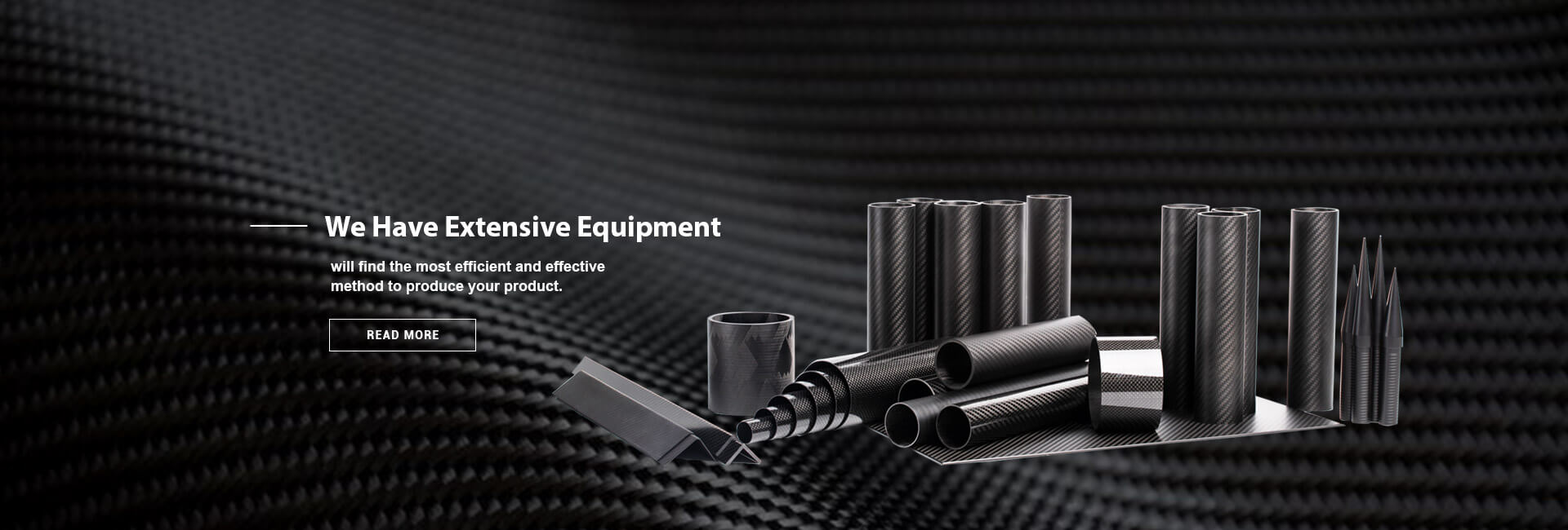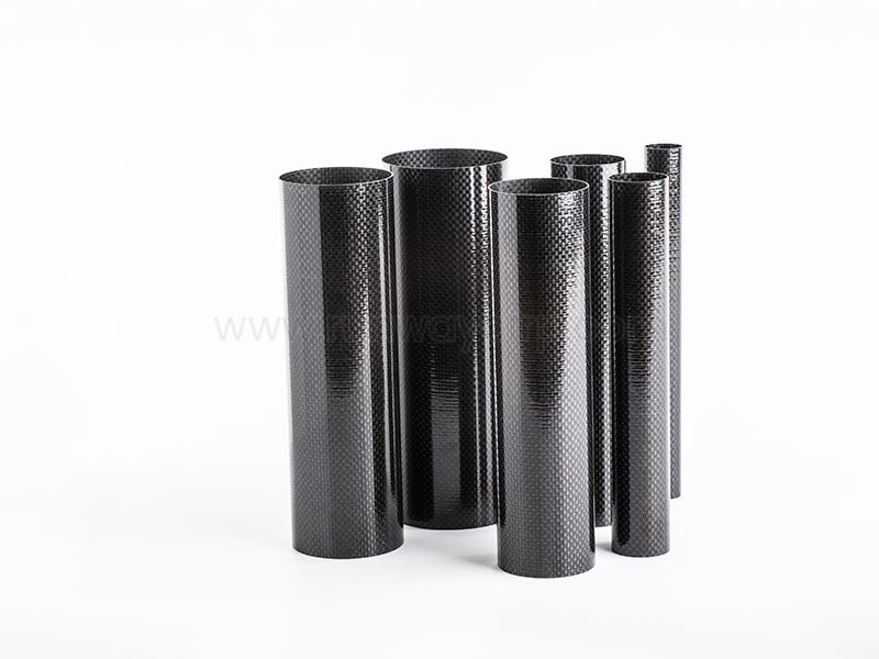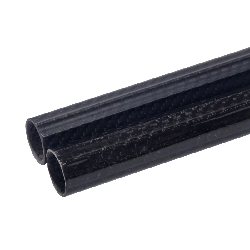
When I compare What are the different types of Carbon Fiber Tubes?, I classify them by four variables: manufacturing process, cross-sectional shape, fiber grade, and fiber orientation. The main categories include pultruded, roll-wrapped, filament-wound, and braided carbon fiber tubes, available in round, square, rectangular, oval, hexagonal, tapered, telescoping, and custom profiles. Each type distributes stiffness, strength, torsion resistance, crush resistance, and cost differently.
Carbon fiber tubes are hollow structural components made from carbon reinforcement embedded in a polymer matrix, usually epoxy or another thermosetting resin. I find them in drone arms, robotic frames, camera equipment, bicycle structures, aerospace assemblies, industrial guards, and telescoping systems. However, the phrase “carbon fiber tube” does not describe one uniform product; two tubes with the same outside diameter can behave very differently because of wall thickness, modulus, fiber angle, resin content, and manufacturing method.
This guide explains the main carbon fiber tube types and provides a practical selection process for engineers, manufacturers, and purchasing teams. I will also cover dimensional inspection, joining, machining, quality documentation, delivery planning, and total cost of ownership so that the final selection is based on operating loads rather than appearance alone.
The different types of carbon fiber tubes are best separated into four manufacturing categories and several profile categories. Pultruded carbon fiber tubes generally place most fibers along the tube axis, making them suitable for axial tension, compression, and bending stiffness. Roll-wrapped carbon fiber tubes use layered prepreg sheets, allowing designers to control fiber angles and combine longitudinal and hoop reinforcement.
Filament-wound carbon fiber tubes are produced by winding resin-impregnated fibers around a mandrel at controlled angles. This method is useful when torsion, pressure containment, or balanced structural loading matters. Braided carbon fiber tubes use interlaced fiber architectures that conform well to curved or complex mandrels and can provide improved damage tolerance compared with a tube made entirely from straight axial fibers.
The second classification is shape. Round tubes are common because their geometry distributes bending and torsional loads efficiently, while square and rectangular profiles simplify frame assembly. Oval, hexagonal, tapered, telescoping, and custom profiles are selected when packaging, nesting, contact area, or aerodynamic clearance controls the design.
| Classification basis | Main types | Primary design effect |
|---|---|---|
| Manufacturing process | Pultruded, roll-wrapped, filament-wound, braided | Controls fiber placement, surface finish, repeatability, and load capability |
| Fiber orientation | Unidirectional, 0°/90°, ±45°, quasi-isotropic | Determines axial stiffness, hoop strength, torsion, and multidirectional behavior |
| Cross-sectional shape | Round, square, rectangular, oval, hexagonal | Affects bending efficiency, assembly, contact, and packaging |
| Modulus grade | Standard, intermediate, high modulus | Changes stiffness, strain capacity, cost, and sensitivity to impact |
| Wall construction | Thin-wall, thick-wall, sandwich, integrated insert | Influences buckling, crushing, connection strength, and weight |
The first step in choosing a carbon fiber tube is to identify how the tube will be loaded. I do not begin with the outside diameter because the same diameter may be acceptable for one application and unsafe for another. The design load should include axial force, bending moment, torsion, shear, external pressure, internal pressure, impact, vibration, and the number of operating cycles.
For example, a drone arm may experience bending and vibration, while a pressure vessel requires controlled hoop reinforcement. A robotic link may combine axial compression and bending, and a telescoping camera pole may require low mass, joint stiffness, abrasion resistance, and repeatable sliding dimensions. These load cases favor different fiber orientations and manufacturing methods.
Record the maximum tensile and compressive forces in newtons.
Record the bending moment in newton-meters.
Record the torsional load in newton-meters.
Define the unsupported length and end conditions.
Estimate the required service life in load cycles.
Identify impact, temperature, moisture, chemicals, and ultraviolet exposure.
Establish the maximum allowable mass and deflection.
Carbon fiber is anisotropic, which means its properties vary by direction. A tube with a large proportion of 0° fibers can have strong axial performance but limited resistance to transverse splitting or torsion if the laminate does not include enough ±45° and hoop reinforcement. I therefore treat fiber orientation as a primary design variable rather than a secondary manufacturing detail.
Choosing by outside diameter only: Always specify OD, ID, wall thickness, length, and tolerance together.
Ignoring compression buckling: A tube can have a high tensile rating but still fail by local or global buckling.
Using tensile data for bending design: Bending requires flexural modulus, section properties, and support conditions.
Leaving out impact loads: A lightweight tube may lose residual strength after local damage even when the surface appears usable.
The manufacturing process determines how carbon fibers are arranged, how accurately dimensions can be held, and which loading directions the tube can support. When I compare carbon fiber tube types, I look at fiber continuity, laminate balance, surface requirements, production volume, tooling cost, and the need for custom dimensions.
Runway manufactures composite products using filament winding, roll wrapping, and pultrusion, and its product range includes carbon fiber tubes, telescopic poles, plates, rods, shapes, and connectors. That combination is useful for buyers who need more than a standard tube because machining support, inserts, end fittings, or related composite profiles may be part of the same project.
Pultruded carbon fiber tubes are manufactured by pulling continuous fibers through resin impregnation and a heated forming die. The die fixes the profile while the resin cures, producing a repeatable cross-section for ongoing production. Most of the reinforcement is usually aligned along the tube axis, although some products include additional transverse or angled fibers.
I select pultruded tubes when axial stiffness, low mass, consistent geometry, and repeatable production are more important than complex laminate tailoring. Typical uses include robotic arms, structural braces, drone booms, lightweight frames, linear guides, and instrument supports. A pultruded tube may be specified with a standard modulus carbon grade and a longitudinal fiber content suited to bending or axial loading.
The main limitation is directional performance. If the application contains significant torsion, internal pressure, local bearing, or crushing at fastener holes, a basic unidirectional pultrusion may require an overwrap, sleeve, metallic insert, or a different laminate architecture.
Roll-wrapped carbon fiber tubes are made by wrapping prepreg or resin-coated carbon sheets around a mandrel. The manufacturer can stack plies at 0°, 90°, and ±45° angles to balance axial stiffness, hoop strength, torsion, and damage resistance. After wrapping, the laminate is consolidated and cured under controlled temperature and pressure.
I use roll-wrapped tubes when the design requires a controlled laminate schedule rather than one dominant fiber direction. A typical layup might combine 0° plies for bending, ±45° plies for torsion, and 90° plies for circumferential stability. The exact schedule depends on load calculations and should be documented in the drawing or purchase specification.
Roll-wrapped construction also supports tapered tubes, custom wall thicknesses, and some non-round profiles. However, tooling, labor, cure control, and inspection requirements can make the process less economical for very large production quantities unless the geometry is standardized.
Filament-wound carbon fiber tubes are produced by winding continuous impregnated fibers around a mandrel at a programmed angle. Low winding angles place more fibers along the axis, while higher angles increase circumferential reinforcement. A balanced winding pattern can support combined axial, hoop, and torsional loading.
The difference between pultruded and filament-wound carbon fiber tubes is mainly fiber placement. Pultrusion is generally optimized for continuous axial reinforcement and fixed profiles, whereas filament winding gives the manufacturer more control over winding angle and circumferential coverage. I would normally consider filament winding for pressure-containing tubes, drive shafts, torsion members, structural shells, and parts that need a tailored angle pattern.
Filament-wound tubes may require additional machining, trimming, or surface finishing after curing. Buyers should ask whether the quoted dimensions refer to cured OD, finished OD, nominal ID, or a post-machined surface. This distinction affects fit, adhesive bond thickness, bearing installation, and replacement compatibility.
Braided carbon fiber tubes use interlaced fibers formed over a mandrel or preform. The braid angle can be adjusted, and the structure can conform to tapered or curved shapes more easily than some straight-sheet methods. Braided preforms are often combined with resin transfer molding, bladder molding, or an overbraid-and-cure process.
I consider braided tubes when the part requires multidirectional reinforcement, complex geometry, or improved resistance to local damage. The braid can provide useful ± angle coverage for torsion and transverse stability, although the final performance depends on braid architecture, fiber volume, resin system, consolidation, and cure quality.
Braided construction is not automatically stronger in every direction. If the primary requirement is maximum axial stiffness at the lowest mass, a carefully designed unidirectional tube may perform better. The correct comparison should use laminate-level test results rather than general statements about braid structure.
After selecting a manufacturing process, I specify the fiber orientation and modulus. Unidirectional carbon fiber tubes place most fibers parallel to the tube axis and are efficient for axial force and bending. They are common in booms, spars, braces, shafts, and structural links where the main load direction is known.
A multidirectional tube may use a combination of 0°, 90°, and ±45° plies. The 0° plies contribute axial and bending stiffness, the 90° plies support hoop and transverse stability, and ±45° plies carry shear and torsion. For a tube exposed to uncertain loading, a balanced laminate is usually easier to validate than a heavily one-directional structure.
Modulus is another separate variable. Standard-modulus carbon fiber often provides a practical balance of stiffness, strain tolerance, and cost. Intermediate- and high-modulus grades can increase elastic stiffness, but they may have different strain-to-failure behavior and higher material costs. I would not specify a high-modulus tube solely because its modulus number is larger; the complete failure mode and impact requirement must be evaluated.
Round carbon fiber tubes are the most common profile because they provide efficient resistance to bending and torsion while maintaining a relatively uniform wall. They are suitable for drone arms, camera poles, bicycle components, aerospace supports, and industrial shafts. Round geometry also works well with filament winding and telescoping assemblies.
Square and rectangular carbon fiber tubes simplify frame construction because their flat sides resist rotation at joints. They are useful for robotic frames, machine guards, equipment supports, and modular structures. The corners require careful inspection because local radius, laminate bridging, and corner consolidation can affect strength and dimensional accuracy.
Oval tubes reduce thickness in one direction while preserving a broader surface in another. This can support aerodynamic packaging, low-profile assemblies, and parts that must fit inside narrow housings. Hexagonal tubes can provide indexing and anti-rotation features, although compatible fittings and machining tools may be less common.
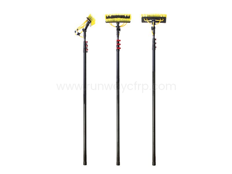
Tapered and telescoping carbon fiber tubes are selected when the structure needs variable diameter, nested sections, or a gradual stiffness transition. Telescoping systems require controlled clearance between mating sections, surface finish, wear resistance, and reliable locking hardware. For these products, I specify both structural performance and sliding performance because a tube that meets a static strength target may still bind or wear during repeated extension.
A load-based selection framework helps prevent the common mistake of selecting a tube by material name alone. The table below links common load conditions with practical tube configurations.
| Dominant load or requirement | Usually suitable tube direction or type | Main design checks |
|---|---|---|
| Axial tension | Pultruded or 0°-dominant roll-wrapped tube | Tensile strength, end termination, hole bearing |
| Axial compression | Pultruded or multidirectional tube | Global buckling, local buckling, end alignment |
| Bending | Pultruded, roll-wrapped, or balanced tube | Flexural modulus, section inertia, fatigue |
| Torsion | Filament-wound, braided, or ±45°-reinforced tube | Shear strength, angle balance, joint transfer |
| Crushing | Thick-wall roll-wrapped or braided tube | Local wall stability, inserts, contact area |
| Internal pressure | Filament-wound tube with hoop reinforcement | Burst pressure, leak testing, winding angle |
| Impact exposure | Braided or multidirectional laminate | Damage tolerance, residual strength, inspection |
| Telescoping motion | Ground or finished tubes with controlled clearance | OD/ID tolerance, wear, locking, contamination |
For bending, I calculate deflection as carefully as ultimate strength. A tube that does not fracture may still be unsuitable if its deflection causes optical misalignment, robotic positioning error, propeller vibration, or contact with adjacent components. For torsion, I examine both the tube wall and the end fittings because many failures occur where torque enters the composite.
Crush resistance deserves separate attention. Thin-wall carbon fiber tubing may perform well in distributed bending but fail under a clamp, bolt head, bearing, or point contact. I reduce this risk by increasing local wall thickness, using bonded or co-cured inserts, adding a sleeve, increasing the contact radius, or designing a load-spreading fitting.
A practical carbon fiber tube specification should state nominal dimensions and measurement methods. I normally list outside diameter, inside diameter, wall thickness, length, straightness, roundness, taper, surface finish, and allowable defects. For a mating assembly, I identify whether the critical dimension is the ID, OD, or both.
The difference between ID and OD measurement is important. A tube may have a controlled OD but a less consistent ID after curing, or the reverse may be true when the inside surface is formed directly on a precision mandrel. If a bearing, plug, shaft, or telescoping section fits inside the tube, the ID tolerance and roundness may matter more than the nominal outside diameter.
Illustrative drawing requirements might include a length tolerance of ±0.5 mm for a short machined part, a diameter tolerance of ±0.10 mm for a precision interface, and a looser ±0.25 mm tolerance for a non-mating structural sleeve. These values are examples for design discussion, not universal limits; the manufacturer should confirm achievable tolerances for the selected process, size, cure method, and post-processing route.
Verify OD and ID at multiple clock positions.
Measure wall thickness at both ends and at the center.
Check straightness over the full reference length.
Inspect for dry spots, wrinkles, voids, delamination, cracks, and resin-rich areas.
Confirm fiber orientation and laminate schedule where specified.
Record mass per unit length for production consistency.
Use ultrasonic inspection when internal defects could affect safety.
Retain dimensional, material, and batch records.
For structural applications, I ask for test evidence that matches the load case. Tensile testing may follow ASTM D3039 or ISO 527, compression testing may use ASTM D6641, and flexural testing may use ASTM D7264 or ISO 14125. These standards do not automatically certify a finished tube, but they provide a controlled basis for comparing laminate or material performance.
Carbon fiber tubes are often cut or drilled during assembly, and poor machining can create cracks, delamination, and fiber pullout. I use diamond-coated or carbide tools, controlled feed rates, dust extraction, and a supported workpiece. The cut edge should be inspected and sealed when needed to prevent moisture ingress or fiber exposure.
Drilling near the tube end requires more care than cutting to length. A hole reduces the effective cross-section and creates a stress concentration, especially under bearing or clamp loads. I avoid placing holes too close to the edge, use bonded inserts where possible, and validate the joint with representative pull-out, bearing, or torsion tests.
Adhesive bonding can distribute loads over a larger area than a single bolt. The joint design should define bond length, adhesive type, surface preparation, bond-line thickness, cure temperature, and environmental exposure. Mechanical fasteners may still be necessary, but they should not be tightened against an unsupported thin wall without a sleeve, insert, or load-spreading washer.
When I compare carbon fiber tubes vs aluminum tubes, I look beyond density. Carbon fiber laminates can provide a strong stiffness-to-weight ratio and corrosion resistance, while aluminum is easier to cut, drill, tap, and repair in many workshop environments. Aluminum also provides more uniform behavior in different directions, whereas carbon fiber requires careful attention to fiber orientation and joint design.
| Factor | Carbon fiber tube | Aluminum tube |
|---|---|---|
| Weight | Often lower for a stiffness-controlled design | Often higher at equivalent bending stiffness |
| Directional stiffness | Tunable through fiber orientation | More uniform by material direction |
| Corrosion | Does not rust, but galvanic isolation may be required | Can corrode depending on alloy and environment |
| Machining | Requires dust control and composite tooling | Generally easier with standard metal tools |
| Thermal behavior | Lower axial thermal expansion in fiber direction | Higher thermal expansion than carbon-dominant laminates |
| Impact response | Can suffer hidden internal damage | Usually shows visible denting or yielding |
| Initial cost | Frequently higher for custom or low-volume parts | Often lower for standard profiles |
| Joining | Adhesive bonding and inserts are common | Welding, bolts, tapping, and rivets are widely used |
| Lifecycle cost | Can reduce mass, corrosion work, or replacement frequency | Can reduce tooling and repair costs |
Carbon fiber tubes vs fiberglass tubes present a different tradeoff. Fiberglass usually costs less and can provide stronger electrical insulation, while carbon fiber generally offers greater stiffness at lower mass. For radio-transparent structures, antenna supports, and electrically isolated housings, fiberglass may be the more suitable material even when carbon fiber has a higher modulus.
Which process will produce the specified profile and laminate?
What OD, ID, wall-thickness, and straightness tolerances are standard?
Can the supplier provide material certificates and batch traceability?
What tests are performed on incoming fibers, resin, and finished tubes?
Are ultrasonic, visual, dimensional, or weight checks included?
What is the minimum order quantity?
What are the tooling charges and ownership terms?
Can the supplier provide cut-to-length, drilling, inserts, or CNC machining?
How are tubes packaged to prevent bending and impact during transport?
What happens if dimensional inspection identifies nonconforming parts?
Runway presents itself as a manufacturer of CFRP and other composite shapes, including tubes, poles, plates, rods, angles, connectors, and related components. Its listed production methods include filament winding, roll wrapping, and pultrusion, while its service scope includes engineering discussion and machining support. For a production order, I would still request a controlled drawing review, sample approval, process description, inspection plan, and written delivery schedule before releasing volume tooling.
The manufacturing sequence usually begins with fiber selection and material preparation. The manufacturer chooses carbon tow, prepreg, resin, braid, or another reinforcement format according to the target modulus, fiber volume, cure system, and laminate design. Moisture control, storage temperature, out-time, and resin shelf life can affect consistency.
The next stage forms the tube around a mandrel or through a die. Pultrusion uses continuous pulling through a shaped die, while roll wrapping builds layers around a mandrel. Filament winding places fibers at programmed angles, and braiding creates an interlaced preform before resin infusion or compression and cure.
Curing converts the resin from a workable state into a solid matrix. Temperature ramp, dwell time, pressure, vacuum, and cooling rate should be controlled according to the resin system. After curing, the tube may be trimmed, ground, machined, drilled, coated, or fitted with inserts.
I evaluate manufacturing quality through both process records and finished-part inspection. A visual inspection alone cannot reveal every internal defect, so safety-critical applications may require ultrasonic testing, coupon testing, or proof testing. The inspection method should be selected according to the consequence of failure, wall thickness, geometry, and expected defect type.
Before ordering carbon fiber tubes, I confirm the following:
Primary load: axial, bending, torsion, crushing, pressure, impact, or combined loading.
Profile: round, square, rectangular, oval, hexagonal, tapered, telescoping, or custom.
Dimensions: OD, ID, wall thickness, length, straightness, and roundness.
Fiber architecture: unidirectional, balanced, braided, filament-wound, or hybrid.
Modulus and resin system: selected for stiffness, strain, temperature, and environment.
Joint design: bonded, bolted, clamped, threaded, insert-based, or hybrid.
Machining: cut length, holes, slots, end faces, surface finish, and edge sealing.
Inspection: dimensional checks, visual inspection, ultrasonic testing, and coupon data.
Compliance: applicable ASTM, ISO, customer, aerospace, or internal standards.
Commercial terms: tooling, minimum order, lead time, packaging, freight, and replacement policy.
What are the different types of carbon fiber tubes? The main types are pultruded, roll-wrapped, filament-wound, and braided tubes, with performance further shaped by fiber orientation, modulus, wall thickness, and cross-sectional profile. Round tubes usually suit general bending and torsion, square and rectangular tubes simplify framing, while tapered and telescoping tubes address packaging and variable-length requirements.
I choose pultruded carbon fiber tubes for repeatable axial or bending applications, roll-wrapped tubes when the laminate schedule requires precise directional control, filament-wound tubes for hoop, pressure, or torsional loading, and braided tubes for multidirectional reinforcement or complex shapes. The final decision should also include ID-versus-OD tolerances, machining, inserts, joining, environmental exposure, inspection, delivery risk, and total cost of ownership.
For engineers and manufacturers, the next step is to create a load-based drawing with measurable requirements rather than requesting a generic carbon fiber tube. Runway can be evaluated as a potential manufacturing partner because its stated capabilities include pultrusion, roll wrapping, filament winding, composite profiles, and machining support. I would request sample data, dimensional records, test methods, production timing, and a complete quotation before selecting the final tube design.
+86 156 9543 6852
Science & Technology Industrial Park, Zhangdian, Zibo, Shangdong, China