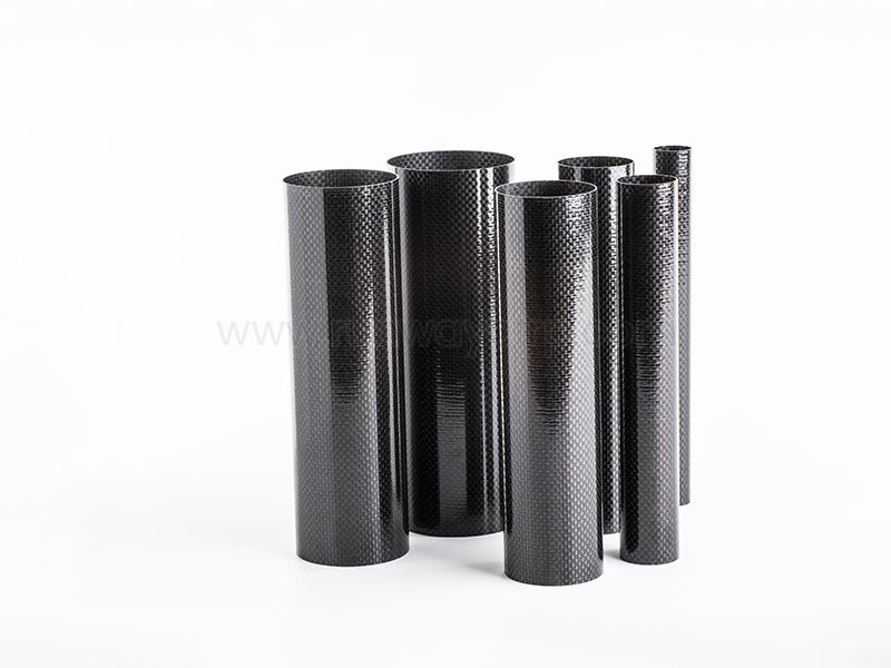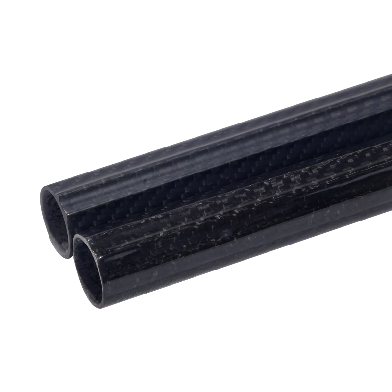
For most UAVs, the best Carbon Fiber Tube is selected by matching outer diameter, inner diameter, wall thickness, fiber orientation, and tube length to the aircraft’s take-off weight, arm span, motor thrust, bending loads, torsion, vibration range, and safety factor. Small racing drones may use thin pultruded tubes, while heavy-lift frames generally require larger roll-wrapped or filament-wound sections. Final sizing should be verified against bending, torsional, vibration, fatigue, impact, and connection requirements before production release.
I treat carbon fiber tubes for UAVs and drones as structural components rather than simple lightweight replacements for metal rods. In a drone frame, a tube may function as a motor arm, fuselage boom, landing-gear support, payload rail, camera mount, or connection between molded nodes. Its performance depends on the complete design: tube geometry, laminate orientation, clamp design, adhesive joint, fastener placement, vibration environment, and production tolerance.
The main reason engineers select carbon fiber is the combination of low mass, directional stiffness, corrosion resistance, and useful fatigue performance when the laminate and joints are correctly designed. A tube with a 20 mm outer diameter and 1 mm wall thickness may behave very differently from a 20 mm tube with a 2 mm wall thickness, even when both use the same nominal carbon fiber material. For professional buyers, I recommend evaluating five areas together: structural loading, manufacturing process, dimensional control, quality documentation, and total cost per usable assembly.
This buyer guide explains what carbon fiber tubes for UAVs and drones are, how they work in different frame designs, how to select dimensions, and how to compare pultruded, roll-wrapped, filament-wound, plate, and molded components. I also cover failure prevention, supplier inspection, indicative pricing, minimum order quantities, and the information I would request before approving a production order.
Carbon fiber drone tubes reduce structural mass while maintaining directional stiffness for arms, booms, and landing gear.
Tube diameter usually controls bending stiffness more efficiently than adding small amounts of wall thickness.
Pultruded tubes suit repeatable straight sections, while roll-wrapped tubes offer broader laminate and orientation control.
Final selection requires take-off weight, arm length, motor thrust, torsional load, vibration, and safety-factor calculations.
Supplier approval should include dimensional tolerances, laminate details, inspection records, sample testing, MOQ, and delivery timing.
Preventing clamp crushing, drilling damage, galvanic contact, and resonance failures lowers replacement and redesign costs.
Before ordering carbon fiber UAV tubes, I prepare a basic load and interface sheet. It should include maximum take-off weight, payload mass, arm length, motor thrust, propeller diameter, landing impact assumptions, tube span, connector type, fastener locations, and operating temperature. For a production UAV, I also record the expected flight hours, annual quantity, acceptable cosmetic defects, and required traceability.
The following information is especially useful when requesting a quote:
Outer diameter and inner diameter
Required wall thickness or allowable mass per meter
Finished length and length tolerance
Fiber orientation and laminate construction
Surface finish, gloss, matte, or sanded condition
Cutting, drilling, chamfering, or CNC requirements
Connector, insert, clamp, or adhesive interface
Estimated monthly and annual volume
Required inspection documents
Target delivery date and packaging requirements
I would not select a tube only by outside diameter. A supplier needs to know whether the tube is used as a cantilevered motor arm, a short compression member, a long unsupported boom, or a landing-gear strut. The same carbon fiber tube may be suitable for one position and unsuitable for another because bending, torsion, impact, and local crushing produce different failure modes.
First, identify the tube’s actual function in the aircraft. A motor arm usually experiences bending from motor thrust and propeller vibration, torsion from motor torque, and local compression around clamps or fasteners. A payload boom may experience bending from a suspended camera or sensor, while landing gear sees short-duration impact loads and repeated fatigue cycles.
Record the following minimum design inputs:
Maximum take-off mass, including battery and payload.
Maximum motor thrust per arm.
Distance from the main frame to the motor centerline.
Distance between clamps, joints, or supports.
Payload offset from the tube centerline.
Expected landing or collision load.
Operating speed and dominant vibration frequencies.
Required safety factor for the application.
A drone arm that is too flexible can allow motor movement, flight-controller vibration, camera blur, and control-loop instability. A tube can remain intact while still causing poor flight performance if its first bending mode overlaps with a motor, propeller, or frame excitation frequency. For this reason, I review both static strength and dynamic stiffness rather than approving a tube from a tensile-strength number alone.
As a starting example, assume a 2.5 kg quadcopter has a 0.35 m arm and produces a peak vertical thrust of 25 N per motor. The simplified arm moment is approximately 8.75 N·m before applying transient factors. If I apply a design factor of 2, the preliminary design moment becomes 17.5 N·m. That figure still requires refinement because motor torque, maneuver loads, clamp spacing, and landing impact can increase the real load.
Using total aircraft weight as the only load input: Motor thrust and arm length determine local bending more directly.
Ignoring payload offset: A camera or sprayer mounted away from the tube axis creates additional bending and torsion.
Selecting by tensile strength only: Tube stiffness, local crushing, fatigue, and vibration often control the design.
Assuming a safety factor without defining the load case: A factor of 1.5 for a controlled laboratory load is not equivalent to a factor of 2.5 for repeated field impacts.
I select carbon fiber tube dimensions in this order: interface diameter, required stiffness, wall thickness, internal clearance, and finished length. The outside diameter must fit motor mounts, clamps, molded sockets, or connector hardware. The inner diameter must provide enough clearance for wiring, inserts, internal sleeves, or a bonded joint without leaving an excessively thin wall.
Common drone frame sizes may range from approximately 8–12 mm outside diameter for small lightweight arms to 25–40 mm for larger multirotor booms and heavy-lift structures. These are starting ranges rather than universal specifications. A 500 mm arm carrying a high payload may require a larger diameter with a moderate wall, while a 150 mm racing-drone arm may prioritize low mass and compact packaging.
Wall thickness affects strength, local crushing resistance, and weight. Typical preliminary values may fall between 0.5 mm and 2.5 mm, depending on diameter, span, load, manufacturing method, and joint design. I request the actual finished wall tolerance because a nominal 1.0 mm wall with a ±0.15 mm variation can create a 30% difference between the lower and upper wall limits.
Fiber orientation also changes behavior:
0° fibers: Improve axial stiffness and bending resistance along the tube length.
±45° fibers: Improve torsional response and resistance to shear-driven damage.
90° or hoop fibers: Improve circumferential support, clamp resistance, and internal pressure stability.
Hybrid layups: Balance bending, torsion, impact resistance, and local connection requirements.
Round tubes provide efficient bending stiffness in multiple directions and are useful for symmetrical arms and booms. Square or rectangular carbon fiber tubes may simplify motor mounting and prevent rotation inside a socket, but their corners can experience stress concentration and impact damage. I usually prefer round tubes where the load direction changes during flight, and I consider square sections where connector indexing, flat mounting surfaces, or anti-rotation features are more important.
For drone arms, diameter often provides a better stiffness-to-mass improvement than simply increasing wall thickness. However, thin walls are more sensitive to clamp crushing, drilling, edge damage, and local buckling. The correct choice is therefore a balance between global stiffness and local connection strength.
Measuring only the outside diameter: Always verify outer diameter, inner diameter, wall thickness, ovality, and straightness.
Ordering excessive length: Extra tube increases mass and may add an unwanted vibration mode.
Using a purely 0° laminate for a torque-loaded arm: Torsion requires adequate ±45° reinforcement.
Ignoring internal access: A tube may meet strength targets but fail to accommodate wiring, inserts, or serviceable connectors.
The manufacturing process should match the load case, quantity, geometry, and tolerance requirement. Pultruded carbon fiber tubes are produced by pulling continuous reinforcement through a resin and heated die. They commonly provide consistent straight profiles and can be economical for repeated standard sections.
Roll-wrapped carbon fiber tubes are made by placing prepreg or impregnated fabric around a mandrel and consolidating the laminate. This method allows more control over fiber orientation, wall construction, surface finish, and custom dimensions. It is often suitable when a drone manufacturer needs a specific balance of 0°, ±45°, and hoop plies.
Filament-wound tubes place continuous fibers under controlled tension around a mandrel. They can be suitable for cylindrical components where circumferential and helical reinforcement are important. Runway identifies filament winding, roll wrapping, and pultrusion among its composite manufacturing techniques, which is useful when one supplier must support different tube designs and production volumes.
Pultruded versus roll-wrapped carbon fiber tubes is not simply a price comparison. Pultrusion may suit a high-volume straight arm with a stable cross-section, while roll wrapping may be more appropriate for a custom tube requiring specific wall thickness, fiber orientation, or local reinforcement. Filament winding can be considered when the design requires controlled helical fiber placement or a repeatable cylindrical structure.
I also compare tube construction with alternatives:
| Component type | Primary advantage | Typical UAV use | Main limitation |
|---|---|---|---|
| Pultruded tube | Repeatable straight profile and scalable production | Standard arms, rods, rails | Limited orientation flexibility |
| Roll-wrapped tube | Custom laminate and wall construction | Long booms, custom frames, payload supports | Process cost may rise at low volume |
| Filament-wound tube | Controlled helical and hoop reinforcement | Cylindrical booms, pressure-like structures | Requires process-specific design review |
| Carbon fiber plate | Flat mounting and easy panel integration | Center plates, brackets, battery decks | Less efficient as a long unsupported beam |
| Molded composite part | Integrated geometry and connector features | Arms, junctions, landing structures | Higher tooling cost and longer development |
Assuming all carbon fiber tubes have the same properties: Fiber volume, resin system, orientation, cure, and void content affect results.
Choosing pultrusion for a highly torsional custom tube without testing: The laminate may require more ±45° content.
Using plate where a tube is structurally more efficient: A flat plate may need more material to resist bending over a long span.
Ignoring production quantity: Tooling and setup costs can change the economic result between prototypes and annual production.
Drone frames are made of carbon fiber because the material can provide directional stiffness at a lower structural mass than many aluminum alternatives. Lower frame mass can increase payload allowance, battery margin, or flight time, although the final result depends on motors, propellers, battery energy, payload, and aerodynamic configuration. Carbon fiber also resists corrosion in humid operating environments, but it is not immune to impact damage, surface cracking, or electrical interaction with metal hardware.
In a multirotor, lower arm mass reduces the inertia that the flight controller must manage during pitch and roll changes. A stiffer arm also helps maintain motor alignment and reduces relative movement between the motor, frame, and sensors. I would still validate vibration performance with accelerometer data or ground testing because a lighter structure can have a higher natural frequency, lower damping, or a resonance close to the operating range.
Carbon fiber tube cutting and drilling should be treated as controlled composite machining. I use diamond-coated or carbide tools, stable fixturing, dust extraction, and low feed pressure to reduce splintering and delamination. After machining, the edge should be inspected under magnification, cleaned, and sealed where required by the adhesive or environmental specification.
Clamps should distribute load over sufficient contact area. Thin-wall tubes can be crushed even when their calculated global bending stress is low, particularly when a narrow clamp applies concentrated radial pressure. I prefer bonded sleeves, internal mandrels, split clamps, or molded connector inserts when the joint load exceeds what a bare tube wall can tolerate.
For bonded joints, the tube surface must be prepared according to the adhesive supplier’s process. Typical controls include abrasion direction, cleaning agent, open time, adhesive mix ratio, bond-line thickness, cure temperature, and fixture alignment. A production process should record batch numbers and cure conditions rather than relying on visual inspection alone.
Many field failures occur at interfaces rather than in the undisturbed tube wall. Drilled holes remove load-carrying fibers and create stress concentrations, while overtightened fasteners can crush the laminate. Carbon fiber also conducts electricity, so direct contact with aluminum can create a galvanic corrosion risk in the presence of moisture.
I isolate carbon fiber from aluminum using suitable coatings, sleeves, washers, sealants, or nonconductive barriers. I also avoid placing holes too close to tube ends or clamp edges unless the joint has been tested. For production UAVs, a simple coupon test using the actual tube, insert, adhesive, clamp, and fastener gives more useful information than a generic material data sheet.
Drilling dry without dust control: Carbon dust can contaminate bearings, electronics, and respiratory spaces.
Using a steel bolt directly against the laminate: Local bearing stress can initiate cracks or crushing.
Overtightening clamps: Torque should be defined and validated with compression or pull-out testing.
Bonding over a glossy surface: The adhesive interface may fail if surface preparation is incomplete.
Leaving cut ends unsealed: Moisture, impact, and handling can increase edge damage over time.
I recommend a staged validation plan. Start with dimensional inspection, then perform coupon or component tests for bending, compression, torsion, pull-out, clamp crushing, and bonded-joint strength. After static testing, evaluate the complete frame under motor operation, payload loading, landing impact, and representative flight cycles.
Useful inspection and test controls include:
Outer and inner diameter measurement at multiple clock positions.
Wall thickness measurement at several locations along the tube.
Straightness and length inspection against drawing tolerances.
Visual inspection for wrinkles, void indications, resin-rich areas, and delamination.
Mass-per-length verification for production batches.
Three-point bending or cantilever deflection testing.
Torsion testing for arms with motor torque or anti-rotation loads.
Resonance testing using accelerometers or impact excitation.
Fatigue testing based on expected flight hours and load cycles.
For dimensional control, a buyer may specify outer-diameter tolerance of ±0.10 mm for precision connector fits, or a more relaxed ±0.25 mm for noncritical sleeves. The correct tolerance depends on the interface, but I avoid accepting “standard tolerance” without a numerical definition.
A tube can pass a static bending test and still fail in service because of fatigue, vibration, impact, or connection damage. For example, a motor arm may experience thousands of vibration cycles during each flight, with additional transient loads during takeoff, landing, and aggressive maneuvering. The test plan should therefore include the actual motor, propeller, mount, connector, and control hardware whenever possible.
Vibration control is also connected to flight performance. If frame acceleration near a flight-controller mounting point exceeds the system’s filtering capacity, the aircraft may show unstable attitude data, blurred imaging, or premature electronic fatigue. I compare measured resonant frequencies with the operating speed range and check whether changes in battery mass or payload shift the system response.
Testing a bare tube but not the assembled arm: Clamps, bolts, adhesives, and motor plates can control failure.
Using one sample for production approval: I prefer multiple samples from separate manufacturing batches.
Skipping impact testing: Carbon composites may show limited visible damage after an impact.
Ignoring temperature and moisture: Resin properties and adhesive performance can change with environment.
Recording only ultimate load: Deflection at working load is often more relevant to flight behavior.
When I compare carbon fiber tube suppliers for drone manufacturers, I request more than a unit price. The quotation should identify the process, fiber type or grade, resin system, dimensions, tolerances, surface finish, cut-length method, packaging, inspection scope, MOQ, sample lead time, production lead time, and replacement policy for nonconforming parts.
Indicative budget ranges vary by diameter, wall thickness, length, finish, process, quantity, and machining. As a planning estimate, standard small tubes may fall around $3–$15 per piece in low quantities, custom mid-size tubes may range from $15–$60 per piece, and larger machined or reinforced sections can exceed $60–$150 per piece. These figures are not purchase quotations; they are early-stage budgeting ranges that should be replaced by a drawing-based supplier quote.
Typical planning timelines may look like this:
| Procurement stage | Indicative timing | Main cost or risk factor |
|---|---|---|
| Standard sample tube | 1–3 weeks | Existing tooling and stock availability |
| Custom prototype tube | 3–8 weeks | Mandrel, laminate design, machining, approval |
| Pilot production | 4–10 weeks | Process stabilization and inspection |
| Repeated production order | 3–8 weeks | Capacity, raw material, batch planning |
| New tooling or molded connector | 6–14 weeks | Tool design, trials, dimensional approval |
MOQ can range from approximately 10–50 pieces for samples or small custom runs to 100–1,000 pieces for repeat production, depending on the process and tooling. I ask suppliers to separate non-recurring engineering, tooling, sample, inspection, packaging, and freight costs. This prevents a low unit price from concealing a large setup charge.
Comparing prices without equal specifications: A 1 mm wall tube and a 2 mm wall tube are not equivalent products.
Ignoring packaging: Long tubes can arrive bent, chipped, or crushed if unsupported during transport.
Accepting a verbal delivery estimate: Request a written sample date, production date, and shipment condition.
Failing to define nonconformance handling: The purchase order should specify inspection, replacement, credit, and corrective-action procedures.
Approving a supplier without sample testing: A production capability statement does not replace dimensional and structural verification.
I use the following decision sequence when selecting carbon fiber tubes for a UAV:
Define the aircraft class: racing, mapping, inspection, agricultural, long-range, delivery, or heavy-lift.
Calculate the tube load case: bending moment, torsion, compression, impact, and fatigue cycles.
Set the interface geometry: outside diameter, inside diameter, connector length, clamp width, and fastener position.
Choose a preliminary wall thickness: verify local crushing and buckling, not only global bending.
Select fiber orientation: include 0° for axial bending, ±45° for torsion, and hoop support where clamps require it.
Compare manufacturing methods: pultruded for repeatable standard profiles, roll-wrapped or filament-wound for custom laminates.
Check vibration behavior: measure or model natural frequencies with motors, payloads, and batteries installed.
Define acceptance criteria: tolerances, straightness, mass, surface defects, documentation, and test samples.
Evaluate supplier economics: MOQ, tooling, unit price, lead time, freight, inspection, and replacement exposure.
Approve a pilot batch: test assembled components before releasing full production.
The best carbon fiber tubes for UAV frames are not necessarily the thickest or most expensive. They are the tubes that meet the required stiffness, strength, local joint resistance, vibration behavior, mass target, and production tolerance at the intended quantity. For small UAV manufacturers, a standard pultruded tube may be the most practical starting point, while commercial drone startups may benefit from a custom roll-wrapped design after the first flight-test data becomes available.
I consider custom carbon fiber tubes for UAVs when standard sizes create excessive adapters, unusable internal space, unnecessary mass, or poor load transfer. Customization can include nonstandard diameter, wall thickness, taper, cut length, drilled holes, bonded inserts, surface finish, colored identification, or a specific fiber orientation. It can also include a complete tube-and-connector assembly rather than a plain tube.
Custom ordering becomes more practical when annual demand is predictable. For example, if a manufacturer uses 2,000 tubes per year, a $2,000 tooling or engineering charge adds approximately $1 per tube before other costs. At 100 pieces, the same charge adds $20 per tube, which may make a standard tube more economical during prototype development.
Runway supports carbon fiber tubes, plates, rods, shapes, connectors, filament-wound products, pultruded products, and CNC machining support. That range can be useful when a UAV design needs matched tubes and plates or requires machining after pultrusion or winding. I would still request drawings, samples, tolerance records, test data, and a documented process review before approving the supplier for flight-critical production.
For incoming inspection, I recommend a lot-based plan instead of checking only one visually acceptable sample. The inspection record should identify the batch, material or process designation, production date, quantity, inspector, measuring equipment, and nonconformance disposition. For critical aircraft structures, the quality plan may include 100% length and visual inspection with sampling for diameter, wall thickness, mass, and mechanical tests.
A practical checklist includes:
Confirm outer diameter at the tube ends and center.
Measure inner diameter using calibrated gauges or a suitable bore instrument.
Check wall thickness at four or more clock positions.
Verify finished length and cut squareness.
Measure straightness over the specified span.
Inspect for cracks, delamination, exposed fibers, wrinkles, pinholes, and deep scratches.
Confirm surface finish and identification markings.
Check connector fit using a master gauge or approved mating component.
Record mass per piece or mass per meter.
Retain sample parts for traceability and failure analysis.
I also ask whether the supplier can provide certificates of conformity, resin or material records, process records, dimensional inspection reports, and mechanical test reports. The required documentation should match the risk level of the UAV. A recreational accessory may need a simpler plan, while a commercial inspection or heavy-lift aircraft should receive stronger traceability and verification.
Carbon Fiber Tubes for UAVs & Drones: Buyer Guide selection should begin with the load case and interface, not with a catalog diameter or a material slogan. I would define take-off weight, arm length, motor thrust, bending moment, torsion, payload offset, vibration range, safety factor, and expected service cycles before choosing outer diameter, inner diameter, wall thickness, length, and fiber orientation.
For most drone structures, a larger diameter can improve bending stiffness efficiently, while additional ±45° reinforcement may be necessary for torsional loads. Pultruded tubes can suit repeatable standard arms, whereas roll-wrapped and filament-wound tubes provide more control for custom UAV structures. Plates and molded components remain useful for center frames, brackets, junctions, and integrated mounting features.
My practical next step would be to prepare a one-page tube specification containing dimensions, laminate, loads, tolerances, joint details, quantity, inspection requirements, and delivery date. Then I would request samples, test the assembled arm or boom, verify vibration behavior, and compare total cost rather than unit price alone. Runway can be considered when a project requires carbon fiber tubes together with plates, connectors, pultruded products, filament-wound sections, or CNC machining support, subject to documented engineering and quality approval.
+86 156 9543 6852
Science & Technology Industrial Park, Zhangdian, Zibo, Shangdong, China