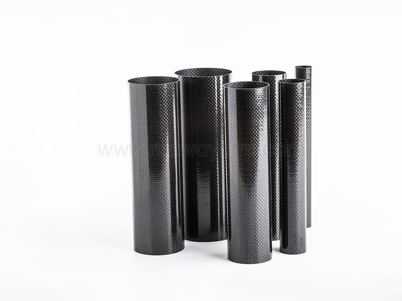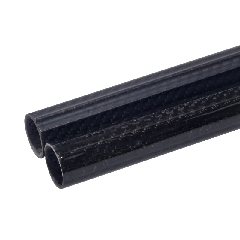
Aerospace-grade Carbon Fiber Tubes are made by selecting qualified fibers and resin, orienting prepreg or continuous fibers on a precision mandrel, consolidating and curing the laminate under controlled temperature and pressure, then removing the mandrel and completing machining, inspection, and mechanical validation. The manufacturing route depends on tube geometry, load direction, production volume, tolerance, and certification requirements.
In this guide, I explain How Aerospace-Grade Carbon Fiber Tubes Are Manufactured from design analysis through material preparation, fiber placement, curing, demolding, finishing, and aerospace composite material testing. I also compare roll wrapping, braiding, filament winding, pultrusion, and compression molding so engineers can match the process to the application instead of selecting a method based only on unit price.
Aerospace carbon fiber tubes require controlled fiber orientation, resin content, curing, machining, inspection, and traceability.
Filament winding suits cylindrical load-bearing tubes, while prepreg roll wrapping supports tailored laminate schedules.
Tube geometry, production volume, tolerance, and load case determine the appropriate manufacturing process and tooling investment.
Aerospace qualification commonly requires material certificates, process records, dimensional reports, non-destructive inspection, and mechanical test data.
Runway manufactures composite tubes using filament winding, roll wrapping, pultrusion, and related machining support.
A supplier comparison should include total cost, validation documentation, production capacity, defect controls, and delivery risk.
I treat an aerospace-grade carbon fiber tube as a controlled structural component rather than simply a tube made from carbon fiber. The designation depends on the complete system: fiber type, resin chemistry, laminate design, process controls, inspection methods, and documentation. A tube intended for an aircraft structure may require different evidence from a tube used in a ground-support fixture or UAV payload boom.
Several technical factors usually determine whether a tube is suitable for aerospace work:
Material traceability: Fiber, resin, prepreg batch, adhesive, and inserts should be traceable to supplier certificates and production records.
Laminate control: Fiber angles, ply count, areal weight, resin content, and ply placement must match the approved design.
Void control: Many structural composite specifications target void content below 1–2%, depending on the laminate and application.
Dimensional control: Outside diameter, inside diameter, wall thickness, straightness, taper, and insert locations must be measured against drawing tolerances.
Process qualification: Cure temperature, pressure, vacuum, dwell time, and post-cure conditions require recorded limits.
Inspection evidence: Visual inspection may be supported by ultrasonic, radiographic, thermographic, or other non-destructive methods.
Mechanical validation: Compression, tension, bending, torsion, buckling, and joint testing should reflect the expected load case.
For engineers, aerospace-grade does not mean that every tube uses the same carbon fiber or resin system. A unidirectional carbon fiber aerospace tube may provide strong axial performance, while a quasi-isotropic laminate may be more appropriate where bending and torsion act together.
I begin with the engineering definition because the manufacturing process cannot be selected correctly without a clear load case. The design package should identify tube length, outside diameter, inside diameter, wall thickness, end conditions, attachment points, environmental exposure, and allowable deformation. It should also state whether the tube carries axial compression, tension, bending, torsion, vibration, impact, or a combination of these loads.
For a cylindrical aerospace structure, the designer should evaluate local buckling as well as material strength. A tube can have sufficient tensile strength but still fail through wall instability under compression. Typical calculations include laminate stiffness, critical buckling load, joint load transfer, insert bearing stress, fatigue life, and thermal expansion.
The design stage also establishes target tolerances. For example, a drawing may specify a diameter tolerance of ±0.10 mm, wall thickness tolerance of ±0.05 mm, straightness within 1 mm per meter, and insert location within ±0.25 mm. These values are examples only; the final requirements must come from the engineering drawing, interface control document, or applicable aerospace specification.
Fiber-reinforced composites are anisotropic, so strength depends strongly on fiber direction. A laminate with 70% of its fibers at 0° may perform efficiently under axial load but provide less resistance to transverse impact than a laminate containing 45° and 90° plies. The tube manufacturing process must therefore support the required fiber architecture rather than forcing the design into a standard pattern.
Designing from outside diameter alone: Wall thickness, internal diameter, laminate sequence, and joint design affect structural behavior.
Ignoring attachment loads: Bonded inserts and bolted joints can create local crushing, peel, and bearing stresses.
Using a generic tolerance: Tight tolerances can increase machining and inspection costs without improving field performance.
Skipping environmental requirements: Moisture, temperature cycling, ultraviolet exposure, hydraulic fluids, and de-icing chemicals may affect resin and adhesive performance.
The material system is selected according to strength, stiffness, toughness, temperature capability, moisture resistance, cure cycle, and cost. Common aerospace carbon fiber choices include intermediate-modulus and high-strength grades, while resin systems may be epoxy, cyanate ester, bismaleimide, or other qualified matrices. Epoxy is widely used because it supports many cure temperatures and offers established processing routes.
I normally separate the laminate into functional regions. Axial plies carry longitudinal tension and compression, hoop plies resist internal pressure or circumferential loads, and ±45° plies support shear and torsion. A representative tube might use a 0°/±45°/90° sequence, but the correct schedule must be calculated through classical laminate theory, finite element analysis, coupon testing, or a combination of these methods.
Material data should include tensile modulus, tensile strength, compressive strength, interlaminar shear strength, glass-transition temperature, density, fiber volume fraction, and moisture-conditioned properties. A cured laminate with a fiber volume fraction near 55–65% may be practical for many structural applications, although the approved process window can differ by resin and reinforcement.
| Material system | Typical advantage | Main limitation | Suitable tube applications |
|---|---|---|---|
| Standard-modulus carbon/epoxy | Balanced stiffness, strength, and cost | Lower stiffness than intermediate-modulus systems | UAV booms, brackets, secondary aircraft structures |
| Intermediate-modulus carbon/epoxy | Increased axial stiffness | Higher material and qualification cost | Aircraft control supports, precision booms |
| High-temperature epoxy | Improved thermal capability | Longer or more demanding cure cycle | Engine-adjacent support components |
| Carbon/cyanate ester | Low moisture uptake and thermal stability | Higher material cost and process complexity | Space and high-temperature aerospace structures |
| Carbon-glass hybrid | Improved impact tolerance and cost control | Lower stiffness than all-carbon laminate | Protective structures and moderate-load tubes |
The mandrel defines the tube’s internal diameter and affects surface finish, dimensional stability, and demolding. Common mandrel materials include steel, aluminum, rubber, silicone, soluble materials, and low-melting alloys. The selection depends on tube length, internal geometry, cure temperature, required surface condition, and whether the mandrel must collapse, dissolve, or slide out after curing.
Before layup, I verify mandrel diameter, straightness, surface finish, release coating, and identification. A release system must prevent bonding between the cured composite and the mandrel without contaminating the laminate. For tubes with internal channels, tapers, or stepped sections, the mandrel may require multiple sections or a collapsible design.
Tooling investment can represent a significant part of the initial project cost. A simple cylindrical mandrel may support repeat production with limited maintenance, while a complex stepped mandrel can require separate fixtures, removable sections, and additional dimensional checks. The supplier should identify tooling life, storage requirements, repair limits, and replacement lead time before purchase approval.
The main aerospace carbon fiber tube manufacturing methods include roll wrapping, braiding, filament winding, pultrusion, and compression molding. Each method controls fiber placement differently and creates different trade-offs among geometry, laminate customization, production volume, tolerance, and cost.
| Manufacturing method | Best suited to | Key strength | Main constraint |
|---|---|---|---|
| Roll wrapping | Straight tubes with tailored ply schedules | Flexible fiber orientation and wall construction | More labor and handling for complex production |
| Braiding | Tubes requiring conformability and damage tolerance | Continuous braided reinforcement over mandrels | Limited control of some highly directional laminates |
| Filament winding | Cylindrical or tapered tubes with repeated geometry | Accurate continuous fiber placement and repeatability | Less convenient for abrupt local features |
| Pultrusion | Constant cross-sections and long lengths | Efficient continuous production | Fixed profile and limited local reinforcement |
| Compression molding | Short, shaped, or heavily featured components | Good consolidation around detailed geometry | Tooling cost and size limitations |
Runway identifies filament winding, roll wrapping, and pultrusion among its composite manufacturing techniques. That process range is useful when a buyer has several tube families, because the supplier can evaluate whether a repeated cylindrical part, a constant profile, or a custom laminate needs a different production route.
In roll wrapping, prepreg sheets are cut into calculated ply shapes and wrapped around a mandrel. The operator controls ply angle, overlap, seam location, and stacking sequence. This method is suitable when the laminate requires multiple orientations or local reinforcement around bonded inserts and end fittings.
The primary risks are ply wrinkling, trapped air, inconsistent overlap, and variation in wall thickness. Vacuum bagging, debulking, and controlled compaction reduce these risks. For a demanding tube, each ply may be identified by orientation and position, while the layup record documents operator, batch, tooling, and inspection status.
Braiding places interlaced carbon fibers over a mandrel, often creating a continuous sleeve with controlled braid angles. It can support efficient load transfer around changes in diameter and may provide useful resistance to impact and damage. Additional unidirectional or hoop reinforcement can be added when the braid alone does not meet axial or circumferential requirements.
Braiding is less suitable when the design requires highly concentrated unidirectional reinforcement over a long straight section. The braid angle, coverage, tow tension, and local fiber distortion must be controlled to avoid resin-rich areas or uneven compaction.
Carbon fiber tube filament winding uses continuous tows guided onto a rotating mandrel. The winding head controls helical angle, band placement, tow tension, traverse speed, and layer count. Low winding angles place more fiber along the tube axis, while higher angles increase hoop and shear capability.
Filament winding is particularly suitable for tubes with consistent cylindrical or tapered geometry. A winding program can repeat the same pattern across many parts, reducing manual ply placement variation. However, openings, flanges, abrupt thickness changes, and complex end features may require secondary reinforcement or post-machining.
Pultrusion pulls continuous fibers through resin impregnation and a heated die to create a constant cross-section. It is efficient for long lengths and repeated profiles, especially where the tube dimensions remain unchanged over the entire part. The process can deliver consistent production rates once the die, pulling speed, resin content, and cure temperature are established.
The main limitation is geometric flexibility. Pultrusion is not the first choice for tubes with variable wall thickness, internal steps, integrated flanges, or localized load pads. Secondary cutting, drilling, bonding, and machining may still be needed after the profile exits the die.
Compression molding places a charge of prepreg, compound, or preformed reinforcement into a heated mold and applies pressure. It is more common for shorter tubes, shaped shells, fittings, and components with complex local details than for very long, thin cylindrical tubes.
The process can produce accurate external features, but tooling costs may be considerable. It also requires careful control of charge placement, resin flow, fiber movement, mold temperature, and cure pressure. Compression molding becomes more attractive when annual volume justifies dedicated tooling.
During layup, I verify material identity, shelf life, thaw time, room temperature, and handling limits. Prepreg is usually stored at a specified low temperature and conditioned before use, while dry fiber systems require controlled resin impregnation. The work area should control temperature, humidity, particulate contamination, and foreign-object debris.
Each ply must follow the approved orientation and shape. The technician should confirm the 0°, 90°, +45°, and −45° directions against the drawing rather than relying on visual estimates. Debulking may be performed after selected ply groups to reduce trapped air and improve contact between layers.
Consolidation quality influences void content and laminate thickness. Vacuum pressure near −0.09 MPa is commonly used in vacuum-bag processes, while autoclave pressure may reach approximately 0.3–0.7 MPa depending on the qualified material system. Actual values must come from the resin supplier’s process specification and the approved manufacturing procedure.
Curing converts the resin from a viscous material into a cross-linked matrix that transfers load between fibers. The cure cycle may include a controlled heat-up rate, dwell period, pressure application, vacuum hold, final cure temperature, and cooling rate. Common aerospace epoxy systems may cure around 120–180°C, but temperature alone does not define a valid cycle.
Thermocouples should be placed at representative hot and cold locations on the tool or part. The production record should capture temperature, pressure, vacuum, time, and any alarms or deviations. A cure cycle that reaches the nominal temperature but contains a pressure loss or uncontrolled exotherm may require engineering review before the part is accepted.
For thicker laminates, resin exotherm can raise the internal temperature above the programmed oven temperature. Cure-cycle development should therefore include thermal measurement and, where necessary, a slower ramp or staged dwell. Differential scanning calorimetry, dynamic mechanical analysis, or resin supplier data can help verify cure state and glass-transition temperature.
After curing and cooling, the tube is removed from the mandrel using the approved demolding method. Force must be controlled because excessive extraction loads can damage thin walls, create delamination, or distort the tube. Internal inspection is especially important when the mandrel has a release film, seam, or collapsible section.
Trimming is normally performed with diamond tooling, abrasive cutting equipment, or CNC machining. Carbon fiber dust is electrically conductive and can irritate skin and lungs, so extraction, protective equipment, and contamination controls are required. Cutting parameters should limit heat generation and prevent fiber breakout at the tube ends.
Machining may include end facing, drilling, slotting, countersinking, tapering, and insert preparation. Hole locations should be measured using calibrated fixtures or coordinate inspection equipment. If a hole is drilled through a laminate, the design may require edge distance, local reinforcement, bushing installation, or a bonded insert to prevent bearing failure.
Many aerospace carbon fiber tubes fail at interfaces rather than in the unmodified laminate. Bonded inserts, end plugs, threaded fittings, clevises, and metallic sleeves transfer loads into the composite wall. The joint design must account for adhesive shear strength, peel stress, thermal expansion, surface preparation, cure pressure, and inspection access.
Before bonding, the composite surface may be abraded, cleaned, dried, and treated according to the adhesive specification. The process record should identify adhesive batch, mix ratio, working life, bond-line thickness, cure temperature, and fixture alignment. A controlled bond-line thickness, such as 0.10–0.30 mm where specified, can be more important than simply applying more adhesive.
The supplier should validate the joint using representative coupons or subcomponents. Tests may include pull-out, axial tension, torsion, bending, fatigue, and environmental conditioning. A tube that meets bare-laminate strength requirements may still be unsuitable if the insert fails at a lower load.
Aerospace composite material testing normally combines dimensional inspection, visual examination, non-destructive inspection, material verification, and mechanical testing. I recommend defining acceptance criteria before production begins, because inspection is more effective when the supplier knows which defects are rejectable, repairable, or subject to engineering review.
Typical dimensional checks include:
Outside diameter and inside diameter at multiple stations
Wall thickness around the circumference
Overall length and cut-end squareness
Straightness, concentricity, taper, and roundness
Hole diameter and positional accuracy
Insert depth, alignment, and pull-out geometry
Surface defects, exposed fibers, blisters, wrinkles, and delamination
For a 1,000 mm tube, the inspection plan might measure diameter every 100–250 mm and check straightness against a defined datum. A supplier should provide calibrated equipment records and an inspection report showing actual readings rather than only a pass/fail statement.
Testing should represent the intended load case. Common evaluations include longitudinal tensile and compression strength, three-point or four-point bending, torsion, short-beam interlaminar shear, fatigue, impact, and compression after impact. Coupon tests can establish laminate allowables, while full-scale tube tests confirm the effect of geometry, joints, holes, and manufacturing variation.
A practical qualification plan may include at least three specimens for early process screening and larger sample groups for formal statistical confidence. The required number depends on the governing specification, risk classification, and customer approval process. Test fixtures must prevent unintended local crushing or eccentric loading, which can produce misleading failure results.
Carbon fiber tube non-destructive inspection may use ultrasonic testing, computed radiography, thermography, tap testing, or visual methods. Ultrasonic inspection can identify delamination, void-rich regions, disbonds, and thickness variation when the tube geometry permits reliable coupling and signal interpretation.
Thin or small-diameter tubes can be difficult to inspect with standard equipment. The inspection procedure should specify probe frequency, calibration standard, scan speed, coverage, sensitivity, and operator qualification. For production parts, the supplier should retain scan records, calibration results, defect maps, and disposition decisions.
Aerospace buyers should request a documentation package that includes:
Certificate of conformity
Material certificates for fiber, resin, adhesive, and metallic inserts
Batch and lot traceability
Layup or winding records
Cure-cycle charts
Dimensional inspection results
Non-destructive inspection records
Mechanical test reports where required
Nonconformance and corrective-action records
Packing and preservation instructions
An AS9100-based quality system can provide an organizational framework for aerospace production, but certification alone does not prove that a specific tube meets the design. I look for the relationship between the quality system, approved process instructions, inspection evidence, and part-level traceability.
I use the following decision framework when comparing processes:
| Requirement | Preferred process direction | Reason |
|---|---|---|
| Constant round tube, repeated geometry, medium-to-high volume | Filament winding | Programmable continuous fiber placement |
| Custom laminate with several fiber angles | Roll wrapping or prepreg layup | Flexible ply-by-ply construction |
| Long constant profile | Pultrusion | Continuous production through a shaped die |
| Variable diameter or local reinforcement | Braiding plus secondary reinforcement | Conforms to changing geometry |
| Short shaped section with molded details | Compression molding | Forms complex external features |
| Tight internal diameter and low machining allowance | Precision mandrel process | Reduces material removal and dimensional variation |
| Low annual volume and changing design | Roll wrapping | Lower dedicated tooling commitment |
| High axial load | Low-angle winding or dominant 0° plies | Aligns fibers with the primary load |
| High torsion | ±45° reinforcement | Increases in-plane shear capability |
| High local joint load | Local prepreg, braid, or molded reinforcement | Distributes insert and fitting stresses |
The best process is not automatically the one with the lowest initial quote. For example, pultrusion may reduce unit cost at several thousand meters per year but become inefficient for a 20-piece prototype program. Filament winding may require programming and mandrel investment, yet reduce repeated layup labor across a production run.
I also compare scrap rate, inspection time, post-machining, tooling maintenance, packaging, freight, and requalification cost. A tube priced at $180 may become a $260 delivered component after machining, inspection, inserts, and packaging, while a $220 tube with integrated end features may reduce assembly labor and total installed cost.
Carbon fiber tubes generally provide a lower density than aluminum and allow designers to place stiffness in selected directions. Carbon/epoxy laminate density is often approximately 1.5–1.7 g/cm³, while common aerospace aluminum alloys are near 2.7–2.8 g/cm³. The weight difference can be meaningful in aircraft, UAV, satellite, and airborne sensor structures.
The comparison is not simply strength against strength. Aluminum is isotropic, electrically conductive, easier to machine, and often simpler to inspect and repair. Carbon fiber is anisotropic, can suffer from hidden impact damage, and may require galvanic isolation when joined to aluminum or other metals.
For a tube governed by axial stiffness, a carbon laminate can reduce mass if its fibers are aligned with the load. For a tube governed by impact, bearing, or complex joint loads, aluminum may remain competitive after considering inserts, protective layers, inspection, and repair access. The correct choice should compare mass, stiffness, fatigue life, environmental durability, manufacturing cost, and replacement cost across the complete assembly.
When evaluating aerospace carbon fiber tube manufacturers, I recommend sending the same technical package to each supplier. The package should include the drawing, laminate schedule, material specification, annual volume, prototype quantity, acceptance criteria, environmental conditions, required documents, and delivery milestones.
I assess suppliers across five categories:
Process capability: Filament winding, roll wrapping, braiding, pultrusion, compression molding, CNC machining, and bonding.
Quality controls: Calibrated measurement equipment, cure monitoring, inspection procedures, nonconformance control, and operator training.
Material management: Refrigerated storage, shelf-life tracking, batch identification, and certificate retention.
Engineering support: Laminate redesign, insert development, tooling analysis, finite element support, and prototype testing.
Delivery risk: Tooling lead time, production capacity, second-source planning, raw material availability, and change-control procedures.
Runway Composite Co., Ltd. is located in Zibo City, Shandong, China, and lists composite tubes, plates, rods, angles, shapes, connectors, telescopic poles, pultruded products, filament-wound tubes, and CNC machining support among its capabilities. Its stated manufacturing methods include filament winding, roll wrapping, and pultrusion, while its product range also includes carbon, glass, aramid, and hybrid reinforcement options.
For an aerospace project, I would still request application-specific evidence before approval. That evidence may include representative tube samples, process capability data, dimensional reports, inspection records, material certificates, cure charts, and a documented plan for qualification testing. A supplier’s general product range is a starting point; aerospace acceptance must be tied to the actual part number and load case.
Delivery risk usually increases when tooling, raw materials, testing, and documentation are treated as separate activities. I reduce this risk by assigning a schedule to each gate: design approval, material release, mandrel completion, first article production, dimensional inspection, mechanical validation, customer review, and serial production.
A practical purchasing schedule may reserve 2–4 weeks for design and drawing review, 3–8 weeks for tooling depending on complexity, 2–6 weeks for prototype production, and additional time for destructive testing or customer approval. These are planning ranges, not guaranteed lead times. International freight, customs clearance, export packing, and rework should be included in the delivery plan rather than added after production.
Total cost of ownership includes more than the tube price. I calculate:
TCO = purchase price + tooling allocation + machining + inserts and bonding + inspection + freight + assembly labor + expected replacement cost
For example, if a carbon tube costs $220, tooling allocation is $18, machining and inserts total $75, inspection is $22, freight is $15, and assembly labor is $30, the installed cost is $380. If the aluminum alternative costs $145 but requires $90 of additional brackets, $55 of corrosion protection, and $40 of assembly labor, its installed cost becomes $330 before considering mass-related operating costs.
Weight savings can change the result in aircraft and UAV programs. If a tube saves 0.8 kg and the platform assigns an operating value of $500 per kilogram saved over its service life, the calculated system benefit is $400. This type of analysis should use the buyer’s actual fuel, payload, endurance, or maintenance assumptions rather than a generic material claim.
How Aerospace-Grade Carbon Fiber Tubes Are Manufactured is best understood as a controlled chain of engineering, material, tooling, processing, finishing, and validation decisions. The manufacturer selects qualified carbon fiber and resin, defines the laminate according to the load case, places the fibers through roll wrapping, braiding, filament winding, pultrusion, or compression molding, and cures the structure under recorded temperature, pressure, vacuum, and time conditions.
After demolding, the tube may require CNC trimming, drilling, bonded inserts, surface preparation, and joint validation. Dimensional inspection, non-destructive testing, mechanical testing, traceability, and acceptance documentation then determine whether the part is suitable for its aerospace application.
My next step would be to prepare a supplier package containing geometry, laminate schedule, load cases, tolerance requirements, annual volume, inspection standards, and documentation expectations. I would compare Runway and other aerospace carbon fiber tube manufacturers against process capability, quality records, tooling plan, delivery schedule, and total installed cost rather than unit price alone.
+86 156 9543 6852
Science & Technology Industrial Park, Zhangdian, Zibo, Shangdong, China