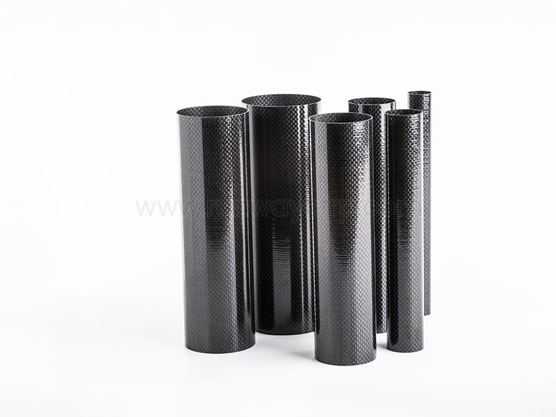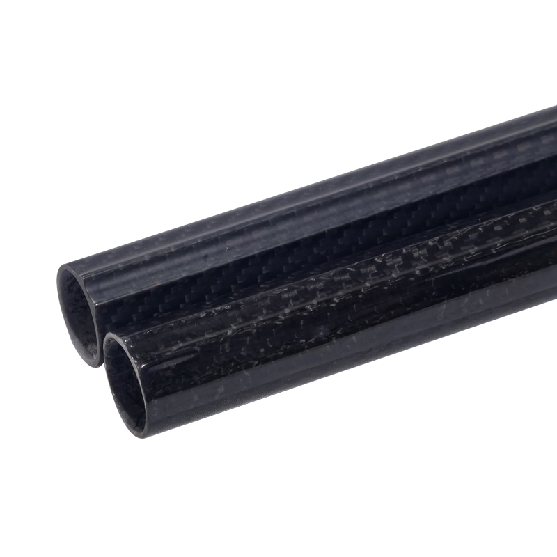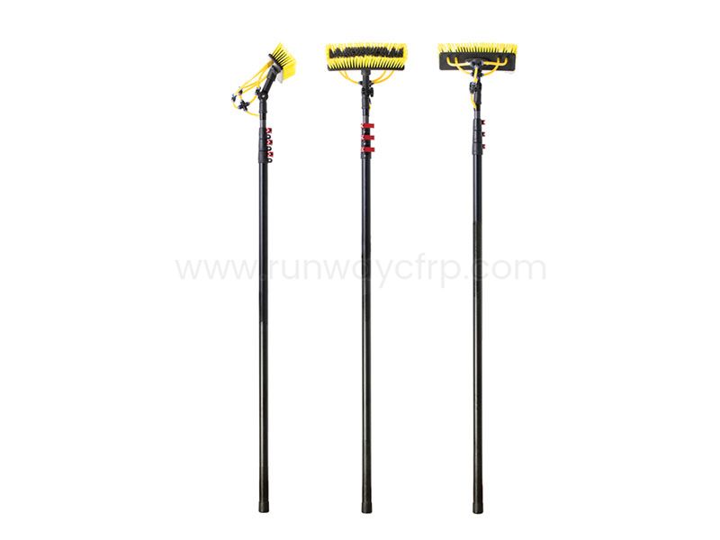
Carbon Fiber Tubes are hollow CFRP structures made from oriented carbon fibers embedded in a polymer resin matrix. Their main advantages are low mass, high directional strength, high stiffness, corrosion resistance, and controlled thermal expansion. Performance depends on fiber orientation, resin system, tube geometry, wall thickness, manufacturing process, temperature, joints, and applied load direction.
In this guide, I explain how carbon fiber tubes work, how manufacturers produce them, how to evaluate carbon fiber tube strength and durability, and how to select or specify a tube for engineering use. I also cover carbon fiber tubes versus aluminum tubes, joining methods, common failure modes, supplier evaluation, and total cost of ownership.
Carbon fiber tubes achieve different strength levels through fiber orientation, wall thickness, diameter, resin selection, and manufacturing method.
Pultruded tubes suit axial loads, while roll-wrapped and filament-wound tubes support customized bending and torsional designs.
Tube sizing must account for compression, bending, torsion, buckling, impact, fatigue, and a documented safety factor.
Bonded inserts and mechanical connectors transfer loads effectively when joint length, surface preparation, and galvanic isolation are controlled.
Professional buyers should verify tolerances, test certificates, inspection records, minimum order quantities, lead times, and total cost.
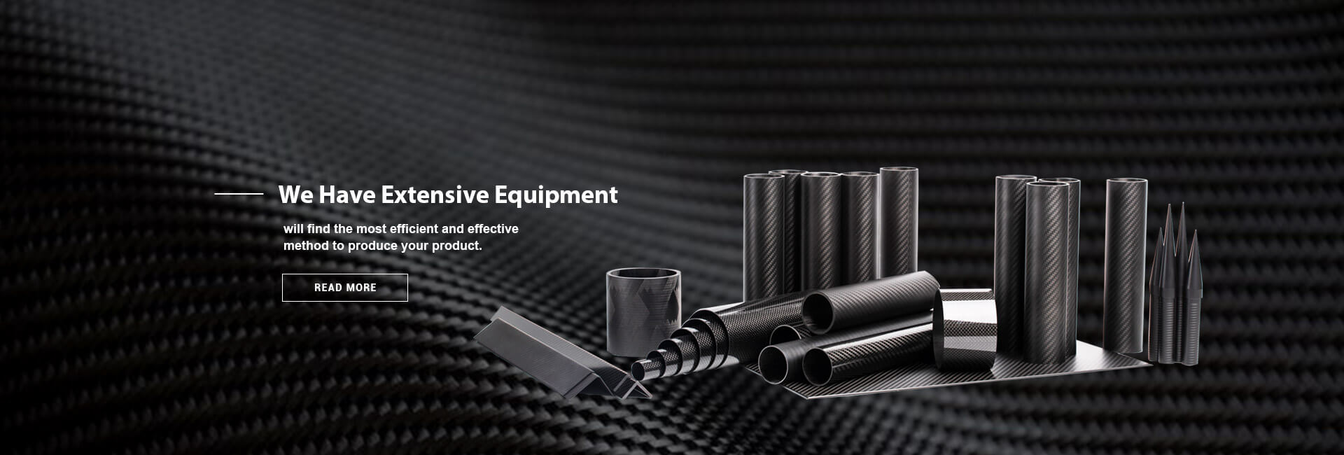
Runway produces composite tubes and structural components using filament winding, roll wrapping, pultrusion, machining, and connector integration.
Before selecting a carbon fiber tube, I recommend defining the complete load case rather than beginning with an outside diameter from a catalog. Record the tube length, supported conditions, axial load, bending moment, torsional load, compression load, impact exposure, operating temperature, humidity, ultraviolet exposure, and expected service cycles. These details determine whether you need pultruded carbon fiber tubes for industrial use, roll-wrapped carbon fiber tubing for lightweight structures, or filament-wound construction for multi-directional loading.
You should also prepare a dimensional specification containing the required inner diameter, outer diameter, wall thickness, straightness, length tolerance, surface finish, hole locations, and end-treatment requirements. If the tube will connect to another part, include the insert material, adhesive type, bond length, fastener pattern, and access for inspection. A tube that meets a nominal diameter requirement may still fail if its joint, bearing area, or unsupported length is not designed correctly.
For production projects, I would prepare at least five documents before requesting quotations:
A drawing with dimensional tolerances and datum references.
A load and environmental requirements sheet.
A material specification identifying fiber type, resin system, and laminate schedule.
A quality plan listing inspection points and test methods.
A delivery plan covering prototype quantities, production quantities, packaging, and required dates.
Start by separating the loads into four primary categories: axial tension, axial compression, bending, and torsion. A tube used as a robotic arm may experience bending and torsion simultaneously, while a support strut may be governed mainly by compression and buckling. A drone boom may experience bending from motor thrust, vibration from rotating components, and local crushing where fasteners or clamps are installed.
For each load, identify the direction of the principal force relative to the tube axis. Unidirectional carbon fibers provide their greatest tensile stiffness and strength along the fiber direction, while ±45-degree layers improve resistance to shear and torsion. A common structural laminate may use a combination such as 0°, ±45°, and 90° plies, but the exact ratio should be determined by the load case rather than copied from another product.
A carbon fiber tube does not have one universal strength value. Tensile strength, compressive strength, flexural strength, and torsional strength can differ substantially because each depends on laminate design, fiber alignment, resin content, defects, and test direction. A tube with a published tensile strength may not have the same allowable value under bending, compression, or a drilled connection.
For preliminary design, I recommend applying a safety factor between 1.5 and 2.0 for controlled, non-critical applications, subject to engineering review. Dynamic, impact-sensitive, aerospace, medical, or life-safety applications may require higher factors, damage-tolerance analysis, coupon testing, and full-scale validation. The safety factor should be applied to the actual allowable design value, not only to a nominal fiber data-sheet value.
Selecting by outside diameter alone: A large diameter with a thin wall may have inadequate local crushing resistance.
Using tensile data for compression design: Compression can be limited by fiber microbuckling, resin instability, joint effects, or global buckling.
Ignoring unsupported length: A tube can have sufficient material strength but still buckle before reaching its compressive capacity.
Treating isotropic metals and composites identically: Carbon fiber tubes have directional properties, while aluminum properties are more uniform around the section.
After defining the loads, choose a preliminary diameter and wall thickness. For bending stiffness, prioritize the outside diameter because the outer fibers carry much of the bending load. For local bearing, impact, clamping, and threaded connections, increase wall thickness or add internal sleeves and localized reinforcement.
Here, (E) is the effective axial modulus, (I) is the section moment of inertia, (K) is the effective-length factor, and (L) is the unsupported length. This equation is a first screening tool; real carbon fiber tubes may require additional checks for laminate instability, ovalization, imperfections, local buckling, and end constraints.
I generally recommend comparing at least three candidate geometries rather than choosing the first available size. For example, a 30 mm outside-diameter tube with a 2 mm wall may provide a different stiffness-to-weight result than a 25 mm tube with a 3 mm wall, even if their masses are similar. The final selection should compare calculated deflection, buckling load, local compression strength, manufacturing tolerance, and joint compatibility.
Tube weight depends on density, circumference, length, and wall thickness. Carbon fiber composite density commonly falls near 1.5–1.7 g/cm³, while aluminum is approximately 2.70 g/cm³ and steel is approximately 7.85 g/cm³. The actual assembly weight may be higher after adding inserts, adhesives, bushings, clamps, protective coatings, and hardware.
A lightweight tube is not automatically an efficient structural tube. If the wall is too thin for the joint or clamp, the design may need metal reinforcement that removes much of the initial weight benefit. I evaluate the complete assembly mass, not the bare tube mass.
Adding wall thickness without checking diameter: This can increase mass without producing the required bending stiffness.
Ignoring dimensional tolerance: A nominal 2.0 mm wall may have a manufacturing tolerance that affects fit and load distribution.
Clamping directly onto a thin wall: Local pressure can crush the laminate even when the global tube load is low.
Failing to check ovality: Excessive ovality can cause uneven bearing, poor insert fit, and premature adhesive failure.
Choose the manufacturing process according to geometry, load direction, production quantity, and dimensional requirements. The main methods used for carbon fiber tubing are pultrusion, roll wrapping, filament winding, and molded or bladder-assisted processes.
| Manufacturing method | Fiber arrangement | Typical advantage | Typical limitation |
|---|---|---|---|
| Pultrusion | Mainly axial fibers | Consistent long lengths and strong axial performance | Limited fiber-angle customization |
| Roll wrapping | Layered 0°, ±45°, and 90° plies | Flexible laminate design and accurate wall construction | More labor and process control requirements |
| Filament winding | Controlled helical and hoop fibers | Good torsional, hoop, and multi-directional performance | Tooling and winding parameters affect lead time |
| Compression or bladder molding | Consolidated molded laminate | Complex shapes and integrated features | Higher tooling cost and process development time |
Pultruded carbon fiber tubes often suit rods, braces, rails, and structural members dominated by axial or bending loads. Roll-wrapped carbon fiber tubes are useful when engineers need controlled fiber orientation, cosmetic surfaces, variable wall construction, or tailored mechanical properties. Filament-wound tubes are suitable for pressure, torsion, hoop stress, and applications requiring circumferential reinforcement.
Manufacturing method affects fiber volume fraction, resin distribution, surface finish, straightness, internal diameter, cut-end quality, and production repeatability. A supplier should explain how the process controls tension, curing temperature, consolidation pressure, resin content, mandrel dimensions, and post-cure conditions.
Runway identifies filament winding, roll wrapping, and pultrusion among its manufacturing techniques for composite tubes and structural components. Its product range also includes plates, rods, angles, shapes, connectors, telescopic poles, and CNC machining support, which can reduce the number of separate vendors required for a multi-part composite assembly.
Choosing pultrusion for a torsion-dominated part: Primarily axial fibers may not provide sufficient ±45-degree shear capacity.
Assuming a woven surface equals a structural laminate: A visible twill or plain-weave layer may be cosmetic or limited in thickness.
Ignoring cure control: Resin-rich or resin-starved regions can change local strength and fatigue behavior.
Ordering production parts before process validation: Prototype tooling and production tooling can produce different tolerances and surface conditions.
Carbon fiber tubes combine carbon reinforcement with a resin matrix, usually epoxy, polyester, or vinyl ester. The carbon fibers carry most of the tensile load, while the resin holds the fibers in position, transfers shear between layers, protects the reinforcement, and determines part of the temperature and chemical resistance. The hollow geometry places material away from the neutral axis, producing efficient bending stiffness at a lower mass than a solid rod.
Carbon fiber tube strength depends on fiber grade, fiber volume fraction, laminate orientation, wall thickness, diameter, cure quality, and test method. A unidirectional laminate may show tensile strengths above 700 MPa and axial modulus values above 70 GPa, while a balanced or woven tube may show lower axial properties but better resistance to torsion, impact, and multi-directional loads. These are representative material ranges, not guaranteed tube allowables.
For engineering procurement, request tube-level data rather than relying only on raw fiber data. Useful tests include tensile testing under ASTM D3039 or ISO 527, flexural testing under ASTM D790, compression testing under ASTM D6641 or ASTM D695, and fatigue testing under a documented cyclic loading procedure. The report should identify specimen geometry, laminate orientation, conditioning environment, failure location, sample count, and statistical treatment.
Carbon fiber tubes do not rust like steel and generally resist many water-based environments, but their durability depends on the resin, coating, joints, temperature, impact exposure, and ultraviolet protection. Repeated cyclic loading can cause matrix cracking, interlaminar damage, fiber breaks, or progressive delamination even when the tube remains visually intact. For fatigue-sensitive products, ask for the number of cycles tested, stress ratio, maximum stress, frequency, temperature, and failure criteria.
Carbon fiber also has a low coefficient of thermal expansion along the fiber direction, but the transverse and resin-dominated directions respond differently. A tube joined to aluminum, steel, or another composite may experience differential expansion during temperature changes. If the application cycles between -40°C and 80°C, for example, the joint design should be evaluated across that range rather than tested only at room temperature.
Treat the joint as a separate engineering component. Carbon fiber tubes can be joined with bonded internal inserts, bonded external sleeves, compression fittings, pinned connectors, bolted flanges, or hybrid adhesive-mechanical systems. The correct choice depends on axial load, bending moment, torsion, service temperature, disassembly requirements, and inspection access.
Bonded inserts typically provide good load distribution because the adhesive transfers force over a longer area. The design should specify bond length, adhesive thickness, overlap length, surface preparation, cure schedule, and allowable operating temperature. Bond gaps commonly need tight control, often within approximately 0.1–0.3 mm depending on the adhesive system and insert geometry.
Drilled holes require special attention because they interrupt fibers and create stress concentrations. Use diamond or carbide tooling, support the tube during machining, seal exposed edges, and inspect for delamination. Avoid placing holes near the tube end or in areas with high bending stress unless the laminate and reinforcement have been designed for that condition.
Many tube failures occur at the connection rather than in the unsupported tube span. A metal insert can create galvanic corrosion when it contacts carbon fibers in the presence of moisture, especially with aluminum. Use a glass-fiber isolation layer, compatible coating, adhesive barrier, anodized or treated metal, and controlled drainage where necessary.
Load transfer should be checked for adhesive shear, insert pull-out, tube bearing, local buckling, peel stress, and fatigue. For production joints, validate the assembly with pull-out, bending, torsion, or combined-load testing. A connector rated for static tension may not provide the same performance under vibration or repeated load cycles.
Bonding contaminated surfaces: Oil, release agent, dust, and uncured resin reduce adhesive strength.
Using a short insert: A short bond length concentrates shear and peel stress near the insert end.
Mixing incompatible materials: Carbon, aluminum, steel, and adhesives require galvanic and thermal compatibility checks.
Over-torquing fasteners: Excessive clamp force can crush the tube wall and initiate delamination.
Leaving drilled edges unsealed: Moisture can enter the laminate and accelerate environmental damage.
Create a failure-mode review before releasing the drawing. Examine delamination, impact damage, crushing, fiber-direction mismatch, fatigue, ultraviolet exposure, thermal cycling, and sudden brittle failure. I also check damage caused during cutting, transportation, clamping, assembly, and service because composite defects may not be visible from the outside.
Delamination can occur between plies when peel or interlaminar shear stress exceeds the laminate capability. Crushing often appears at clamps, inserts, supports, or fastener locations where force is applied over a small contact area. Fiber-direction mismatch occurs when the laminate is designed for axial force but the actual part experiences torsion, transverse loading, or angled impact.
Carbon fiber tubes can retain their shape after impact while suffering internal damage. A dropped tube may show only a small surface mark but contain crushed fibers or interlaminar separation. For safety-sensitive parts, use visual inspection together with tap testing, ultrasonic inspection, radiography, or another method suited to the laminate and geometry.
Ultraviolet exposure can degrade the resin and surface finish over time, particularly when the tube is used outdoors without a protective coating. Specify a UV-resistant clear coat, painted finish, or surface veil where required. For marine applications, also evaluate saltwater exposure, moisture ingress, dissimilar-metal joints, and drainage.
Accepting cosmetic inspection as structural inspection: Surface appearance cannot confirm internal laminate condition.
Ignoring impact history: Mark and isolate tubes that have been dropped or struck.
Using one laminate for every application: Aerospace, robotics, sports, marine, and industrial loads require different damage assumptions.
Testing only static strength: Fatigue, temperature, moisture, and impact may control service life.
Carbon fiber tubes versus aluminum tubes is not a simple material substitution decision. Carbon fiber commonly provides a lower density and higher directional stiffness-to-weight ratio, while aluminum provides more uniform behavior, easier machining, lower initial material cost, and more predictable ductile deformation. The better choice depends on the load case, production quantity, joining method, inspection requirements, and service environment.
| Factor | Carbon fiber tube | Aluminum tube |
|---|---|---|
| Density | Approximately 1.5–1.7 g/cm³ | Approximately 2.70 g/cm³ |
| Directional stiffness | Can be tailored through fiber orientation | More uniform in all directions |
| Corrosion | Carbon does not rust; joints require isolation | Requires alloy and surface-treatment control |
| Fatigue | Depends strongly on laminate and defects | Depends on alloy, stress range, and surface condition |
| Impact behavior | May suffer hidden delamination or brittle damage | Usually shows more visible denting and plastic deformation |
| Thermal expansion | Very low along selected fiber directions | Higher and more uniform than axial CFRP |
| Machining | Requires dust control and edge protection | Generally simpler and faster |
| Initial cost | Often higher for low volumes | Usually lower for standard sizes |
| Customization | Fiber orientation and wall structure can be tailored | Geometry is easier to standardize and extrude |
| Best fit | Weight-sensitive, stiffness-sensitive, corrosion-sensitive designs | Cost-sensitive, easily repairable, general-purpose structures |
For example, replacing an aluminum tube with carbon fiber may reduce mass, but the total assembly savings may be smaller after adding inserts and protective hardware. If a 2 kg aluminum subassembly becomes a 1.2 kg composite assembly, the 0.8 kg reduction may justify the material cost in drones, robotics, aircraft interiors, or moving mechanisms. In a stationary industrial frame, the same reduction may not recover tooling, inspection, and development costs.
Use application requirements to narrow the material and process options. Hobby projects and prototypes may prioritize availability, low minimum order quantities, and simple cutting. Industrial products usually require dimensional repeatability, batch records, inspection documentation, and stable supply over multiple production cycles.
| Application | Recommended focus |
|---|---|
| Drones | Low mass, motor-mount reinforcement, vibration resistance, impact inspection |
| Robotics | Bending stiffness, torsional rigidity, connector design, repeated-cycle fatigue |
| Aerospace components | Traceability, documented testing, damage tolerance, temperature control |
| Automotive | Impact, vibration, thermal cycling, production repeatability, cost per assembly |
| Marine equipment | Moisture resistance, UV protection, galvanic isolation, sealed ends |
| Sports equipment | Deflection tuning, impact response, surface finish, user safety |
| Medical equipment | Cleanability, dimensional control, biocompatibility of exposed materials, inspection |
| Industrial supports | Buckling resistance, load capacity, fire or temperature requirements, service access |
For robotics applications, I would usually prioritize the stiffness-to-mass ratio and joint repeatability because the tube affects actuator loads, positioning accuracy, and dynamic response. For aerospace components, I would require material traceability, process records, environmental conditioning, and a defined non-destructive inspection plan. For high-temperature applications, the resin glass-transition temperature must exceed the service temperature with an appropriate margin.
A tube selected for hobby use may not meet the documentation requirements of an aerospace or medical buyer. Conversely, an aerospace-grade qualification program may be unnecessary for a prototype that will be used for only a few hundred cycles. Application-specific selection prevents both under-design and avoidable procurement cost.
Custom carbon fiber tubes can be produced with nonstandard diameters, wall thicknesses, lengths, fiber angles, end features, surface finishes, internal liners, inserts, and connectors. I recommend sending a supplier a complete drawing instead of requesting “a strong carbon tube,” because the supplier cannot calculate a meaningful proposal without dimensions, load direction, environmental conditions, and interface details.
Include these specifications in the request:
Outside diameter and inside diameter.
Wall thickness and permitted variation.
Length, straightness, concentricity, and ovality.
Fiber type, resin system, and laminate orientation.
Required tensile, flexural, compression, or torsional performance.
Operating temperature and environmental exposure.
End cuts, holes, slots, threads, inserts, or bonded fittings.
Surface finish, coating, color, and marking.
Inspection method and acceptance criteria.
Prototype quantity and expected annual volume.
Packaging requirements and delivery milestones.
Runway describes capabilities covering composite tubes, filament-wound carbon fiber tubes, pultruded products, plates, rods, shapes, connectors, and CNC machining support. This combination is relevant when a project needs both tubular material and finished interface components, but I would still request drawings, test data, inspection records, and production samples before approving a new supplier.
Customization changes cost and delivery risk. A standard tube may be available with a shorter lead time, while a custom mandrel, special laminate, integrated insert, or CNC-machined end can add tooling and validation stages. Ask the supplier to separate one-time tooling charges, prototype charges, unit pricing, finishing, packaging, testing, and shipping.
For small manufacturers, a reasonable sourcing plan may be 2–5 prototype pieces for fit and load testing, followed by a pilot batch of 10–50 pieces before a larger production order. The exact quantity depends on the application, but staged purchasing reduces the risk of discovering dimensional or joint problems after committing to hundreds of parts.
Requesting a custom tube without a load case: This causes price comparisons between products that are not functionally equivalent.
Ignoring minimum order quantity: Custom mandrels and special materials may require a production threshold.
Approving samples without measured reports: The sample should verify dimensions, surface condition, mass, and critical features.
Treating cosmetic carbon weave as a specification: The structural laminate must be identified separately from the visible finish.
I assess a carbon fiber tube manufacturer using measurable production and quality information. Request certificates for the raw carbon fiber and resin, batch or lot identification, cure records, dimensional inspection reports, test results, nonconformance procedures, and sample retention policies. If the part is safety-sensitive, require a first-article inspection and define corrective-action timing before the purchase order is issued.
A buyer checklist should include:
| Supplier criterion | Evidence to request |
|---|---|
| Material control | Fiber and resin batch records |
| Process control | Winding, wrapping, pultrusion, and cure parameters |
| Dimensional control | Diameter, wall thickness, length, straightness, and ovality records |
| Mechanical validation | Test method, sample count, conditioning, and failure data |
| Surface inspection | Visual criteria, defect limits, and repair policy |
| Machining control | Tooling method, hole position, edge finish, and delamination inspection |
| Delivery control | Production schedule, capacity statement, packaging plan, and shipment milestones |
| Traceability | Part marking, lot number, and retained records |
| Corrective action | Nonconformance report process and response time |
| Commercial terms | Minimum order quantity, tooling ownership, warranty, and replacement terms |
Delivery risk is not limited to shipping time. It can also result from unavailable fiber grades, delayed tooling, failed samples, insufficient curing capacity, machining rework, packaging damage, or unclear approval procedures. I reduce this risk by defining prototype, pilot, and production gates, with dimensional and mechanical acceptance criteria at each stage.
For overseas sourcing, maintain schedule allowance for drawing clarification, sample transit, customs, inspection, and corrective actions. A supplier that quotes 20 production days may still require an additional 10–20 calendar days for approval, freight, and receiving inspection, depending on the order and destination. The purchase plan should use the complete elapsed time rather than the factory-only estimate.
The Ultimate Guide to Carbon Fiber Tubes: Strength, Durability, and Customization leads to one practical conclusion: the right tube is selected by load case, geometry, laminate, joint design, environment, inspection requirements, and total cost rather than by appearance or diameter alone. Carbon fiber tubes can reduce mass and increase directional stiffness, but those benefits depend on correct fiber orientation, adequate wall thickness, stable manufacturing, and controlled connections.
My recommended next steps are straightforward. First, document the axial, bending, torsional, compression, fatigue, impact, temperature, and environmental requirements. Second, compare at least three tube geometries and manufacturing methods using calculated stiffness, buckling resistance, mass, and joint capacity. Third, request supplier evidence covering material batches, dimensional tolerances, mechanical tests, inspection records, minimum order quantities, lead times, and corrective-action procedures.
For standard industrial parts, pultruded carbon fiber tubes may provide an efficient starting point. For custom structural assemblies, roll-wrapped or filament-wound construction can provide greater control over fiber direction and wall design. Runway is a relevant supplier to evaluate for composite tubes, structural shapes, connectors, and machining support, provided the final selection is based on verified drawings, samples, test data, and production controls.
+86 156 9543 6852
Science & Technology Industrial Park, Zhangdian, Zibo, Shangdong, China