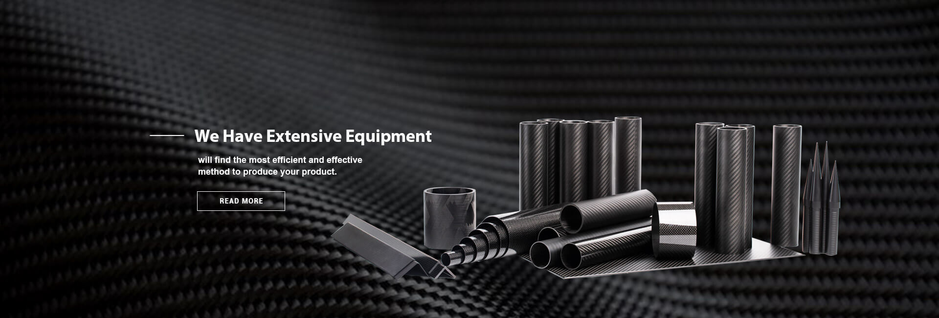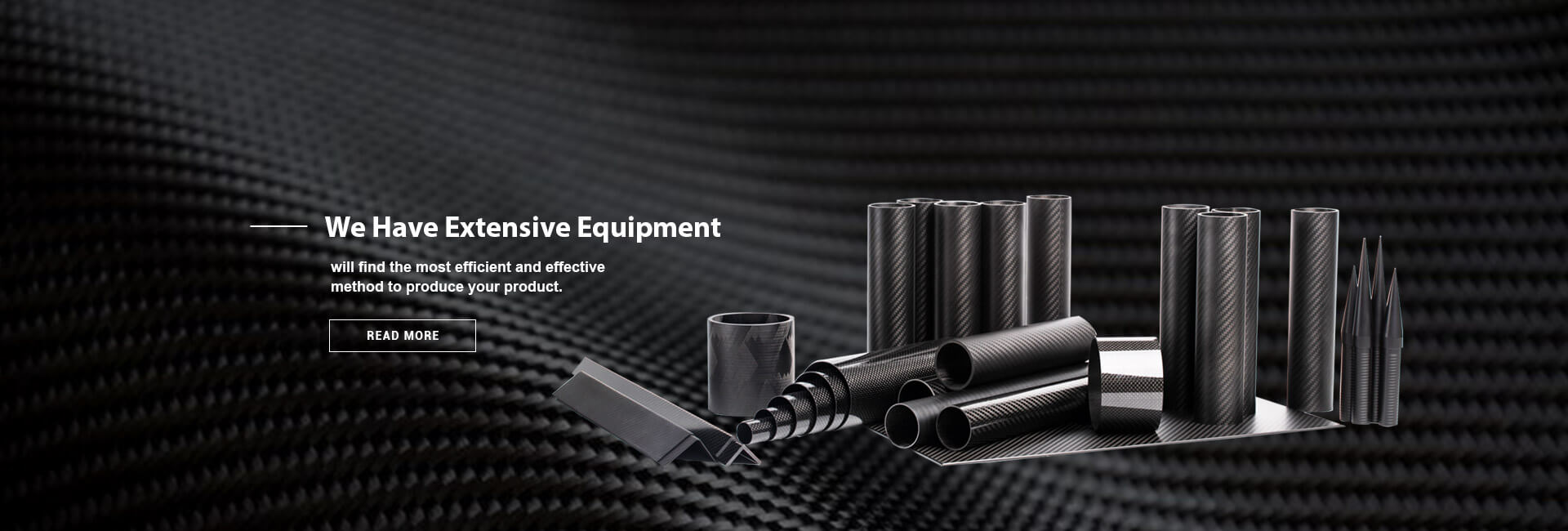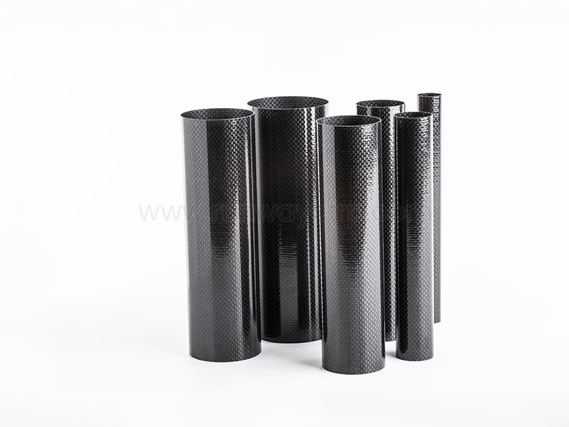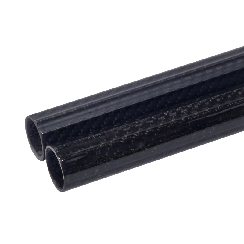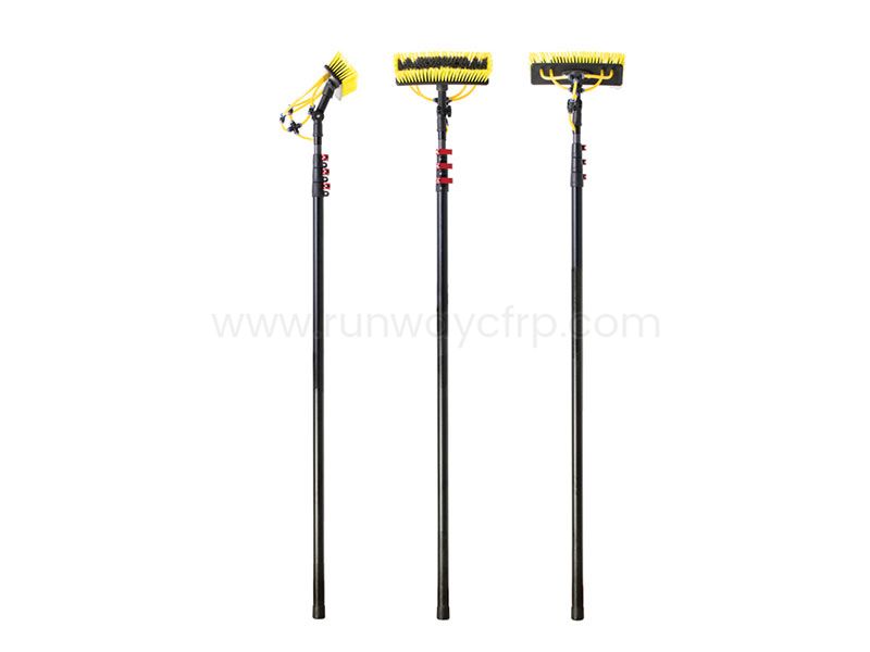
Carbon Fiber Tubes are hollow structural components made from carbon fibers embedded in a polymer resin matrix. They are used when engineers need lower mass, controlled stiffness, corrosion resistance, and directional strength in a tubular form. Their main trade-off is that material and manufacturing costs are usually higher than aluminum, while impact damage, drilling, joining, and repair require more careful engineering.
Carbon fiber tubes appear in aerospace structures, robotic arms, drone frames, telescoping poles, medical equipment, automotive components, marine systems, and sporting goods. However, selecting the correct tube involves more than comparing outside diameter and price. Fiber orientation, wall thickness, resin system, load direction, joint design, inspection requirements, and expected damage exposure all affect whether a tube will perform safely over its intended service life.
Carbon fiber tubes provide high stiffness-to-weight performance, but they require application-specific fiber orientation and wall thickness.
Pultruded tubes suit straight axial loads, while roll-wrapped and filament-wound tubes support broader structural designs.
Aluminum is easier to machine and repair, whereas carbon fiber usually reduces mass and thermal expansion.
Tube connections need inserts, bonded joints, sleeves, or clamps designed to prevent local crushing and delamination.
Lifecycle cost depends on weight savings, service life, inspection, tooling, repairability, and production volume—not purchase price alone.
A carbon fiber tube is a hollow composite profile formed by combining carbon fiber reinforcement with epoxy, polyester, vinyl ester, or another polymer resin. The fibers carry most of the tensile and bending load, while the resin transfers stress between fibers, preserves the tube shape, and protects the reinforcement from environmental exposure. Unlike isotropic metals, carbon fiber tubes have properties that vary significantly with fiber direction.
The most common construction uses unidirectional fibers aligned along the tube axis, combined with ±45-degree layers and, in some designs, 90-degree hoop layers. Axial fibers increase tensile stiffness and compression capacity, angled fibers improve torsional resistance, and hoop fibers help resist splitting, radial pressure, and clamp loads. A tube designed only for axial tension may therefore be unsuitable for torque, impact, or concentrated bearing forces.
Typical carbon fiber tube density is approximately 1.5–1.7 g/cm³, compared with about 2.7 g/cm³ for aluminum and approximately 7.8 g/cm³ for carbon steel. The actual weight advantage depends on the required stiffness, wall thickness, safety factor, fittings, and manufacturing method. A thinner metal tube may be cheaper, but a composite tube can provide lower mass when the design is governed by bending stiffness or vibration control.
Low mass is one of the clearest reasons to specify carbon fiber tubing. Carbon fiber composites can weigh roughly 40% less than aluminum at equal volume, although equal structural performance must be assessed using the complete laminate and joint design. For portable equipment, drones, telescoping poles, and robotic systems, lower tube mass can reduce motor demand, operator fatigue, transport cost, and supporting-structure requirements.
High stiffness-to-weight ratio is especially important in beams, arms, frames, and long tubes that must resist bending or deflection. Standard carbon fiber laminates may provide longitudinal elastic modulus values in the range of approximately 70–150 GPa, depending on fiber grade, fiber volume fraction, resin, and orientation. The tube’s bending stiffness depends on the laminate modulus and the second moment of area, so outside diameter often has a major effect on deflection.
Directional strength allows engineers to place reinforcement where loads occur. A tube with 60–80% of its fibers oriented along the axis may perform efficiently under tension and compression, while additional ±45-degree layers can improve torque capacity. This design flexibility is useful for aerospace booms, robotic links, drive shafts, camera poles, and lightweight structural supports.
Carbon fiber tubes also provide corrosion resistance against water, salts, and many industrial environments. The carbon reinforcement itself does not rust, and the cured polymer matrix does not oxidize like steel. The tube can still suffer resin degradation, moisture-related interface problems, ultraviolet exposure, chemical attack, or galvanic corrosion when connected directly to aluminum or other conductive metals.
Another benefit is relatively low thermal expansion along the fiber direction. Many carbon fiber laminates have near-zero or even negative longitudinal coefficients of thermal expansion, depending on fiber type and layup. This helps reduce dimensional change in optical supports, inspection equipment, precision motion systems, and aerospace structures exposed to temperature variation. Transverse expansion can be substantially higher, so the complete laminate must be evaluated rather than assuming the entire tube is dimensionally stable.
The first limitation is cost. Carbon fiber tow, resin, tooling, curing, finishing, and inspection generally cost more than standard aluminum extrusion or steel tubing. For low-volume custom tubes, tooling and engineering charges may represent a larger share of total cost than the raw material. A realistic comparison should include machining, coating, corrosion protection, replacement frequency, shipping weight, and assembly labor.
Carbon fiber is also sensitive to impact damage that may not be visible from the outside. A dropped tube can develop delamination, matrix cracking, fiber breakage, or internal crushing while retaining an apparently acceptable surface appearance. For safety-critical parts, visual inspection should be supplemented with tap testing, ultrasonic inspection, thermography, or another validated non-destructive testing method.
Brittleness relative to metals is another consideration. Carbon fiber tubes can carry substantial tensile and bending loads, but they do not usually yield gradually in the same way as aluminum or mild steel. Failure may occur through fiber fracture, local buckling, delamination, or resin cracking after the design limit is exceeded. Engineers should define allowable loads, impact limits, damage tolerance, and safety factors instead of relying only on nominal tensile strength.
Repair is more complicated than with metal tubing. A bent aluminum tube may be straightened or replaced with a simple bracket, while damaged composite may require removal of loose material, scarf preparation, new reinforcement, controlled bonding, and post-cure verification. For field equipment, a replaceable tube section or mechanical sleeve can reduce downtime compared with attempting an on-site laminate repair.
Electrical behavior must also be considered. Carbon fiber is electrically conductive, although its conductivity is lower and more anisotropic than copper or aluminum. When carbon fiber touches aluminum in the presence of moisture, galvanic corrosion can occur at the aluminum component. Electrical isolation using glass-fiber layers, polymer bushings, coatings, washers, or sealed adhesive joints may be required.
Manufacturing method determines fiber alignment, surface finish, dimensional control, production volume, and suitable load cases. The principal methods are pultrusion, roll-wrapping, filament winding, and braiding. Each method produces a different balance of axial strength, hoop strength, torsional capacity, tolerance, and tooling cost.
Pultrusion draws continuous fibers through a resin bath or resin-injection system and then through a heated die that forms and cures the profile. The process is efficient for constant cross-sections and places a large proportion of fibers along the tube axis. It is therefore well suited to straight tensile and bending members, rods, rails, structural channels, and repeated production.
Pultruded tubes can provide consistent outside dimensions and relatively low unit cost at sufficient production volume. However, a tube designed primarily for axial properties may have limited resistance to transverse splitting, impact, or high torque unless ±45-degree and hoop reinforcement is included. When specifying pultruded carbon fiber tubes, request the fiber orientation, resin type, wall thickness tolerance, straightness tolerance, and test method used for mechanical data.
Roll-wrapping places prepreg or resin-impregnated carbon fabric around a precision mandrel. Individual layers can be oriented at 0, ±45, and 90 degrees to produce a laminate matched to axial, bending, torsional, and radial loads. After wrapping, the tube is consolidated under pressure and cured before being removed from the mandrel and finished.
This process is useful for custom dimensions, controlled wall construction, cosmetic surfaces, and relatively complex laminate schedules. It also supports internal diameter control through mandrel selection. Compared with a basic pultruded profile, roll-wrapped tubing may offer greater control over load-specific properties, but labor, tooling, trimming, and inspection can increase the price.
Filament winding places resin-coated continuous fibers onto a rotating mandrel at programmed angles. Low winding angles increase axial contribution, while higher angles improve hoop and torsional performance. The process is commonly used for tubes with repeated geometry, pressure-related loading, drive shafts, tanks, and tubular structures requiring controlled fiber placement.
Filament winding is especially useful when a manufacturer must produce a repeatable laminate with a defined angle schedule. The design still requires analysis of resin content, fiber tension, overlap, cure shrinkage, end effects, and local reinforcement near fittings. A nominal winding angle alone does not establish load capacity without laminate thickness and material test data.
Braiding interlaces fibers around a mandrel, creating a structure with strong ±45-degree reinforcement. Braided carbon fiber tubes can be useful for impact tolerance, torsion, complex transitions, and overbraided molded components. They may be combined with unidirectional layers to improve axial strength or with glass fiber to reduce electrical conductivity and material cost.
Runway Composite Co., Ltd. identifies filament winding, roll-wrapping, and pultrusion among its production methods. Its product range includes carbon fiber tubes, filament-wound tubes, pultruded products, telescopic poles, plates, rods, angles, connectors, accessories, and CNC machining support. The company also indicates that it can work with carbon, glass, aramid, and hybrid reinforcements, which may be relevant when a project needs different electrical, impact, or cost characteristics.
The correct carbon fiber tube begins with the load case rather than the catalog size. Record axial tension, axial compression, bending moment, torsion, external pressure, clamp load, impact exposure, temperature range, moisture, chemical contact, and expected service cycles. Also identify whether the tube is a primary load-bearing member or a protective enclosure with limited structural responsibility.
| Load case | Useful construction features | Main design concern |
|---|---|---|
| Axial tension | High proportion of 0-degree unidirectional fibers | Fiber termination and joint efficiency |
| Axial compression | Axial fibers with adequate wall thickness | Local buckling and end crushing |
| Bending | Large outside diameter with 0-degree reinforcement | Deflection, ovalization, and impact damage |
| Torsion | ±45-degree layers around the tube | Splitting and interlaminar shear |
| Radial clamp load | 90-degree hoop reinforcement and local sleeves | Crushing and delamination |
| External pressure | Balanced laminate and sufficient wall thickness | Buckling and collapse |
| Repeated impact | Tough resin, hybrid fibers, protective overwrap | Hidden delamination and inspection |
A useful preliminary calculation for a thin-walled circular tube is the area moment of inertia, (I \approx \pi D^3t/8), where (D) is mean diameter and (t) is wall thickness. For a simply supported beam with a central load, deflection can be estimated using (\delta = PL^3/(48EI)), although actual composite tubes require correction for shear deformation, joints, local damage, and nonuniform laminate properties. These equations are screening tools, not substitutes for laminate analysis or physical testing.
Safety factors must reflect uncertainty and failure consequences. A consumer accessory may use a different design margin than an aircraft structure, medical support, or industrial lifting component. Ask for coupon data using standards such as ASTM D3039 for tensile properties, ASTM D6641 for compression, ASTM D7264 for flexural properties, ASTM D2344 for short-beam interlaminar strength, and ASTM D7136 for impact response where applicable.
The difference between carbon fiber tubes and aluminum tubes is not simply “lighter versus heavier.” Aluminum is isotropic, easy to cut, drill, tap, bend, weld, and recycle, while carbon fiber is anisotropic and must be oriented around the expected loads. Carbon fiber usually offers better stiffness per unit mass, but aluminum often offers lower acquisition cost and easier field modification.
| Factor | Carbon fiber tube | Aluminum tube |
|---|---|---|
| Density | Approximately 1.5–1.7 g/cm³ | Approximately 2.7 g/cm³ |
| Elastic modulus | Often 70–150 GPa longitudinally, laminate-dependent | Approximately 69–73 GPa |
| Strength direction | Tailored by fiber orientation | Similar in all directions for a given alloy and condition |
| Corrosion | No rust; galvanic risk with metals | Oxide protection; pitting possible in aggressive environments |
| Thermal expansion | Low along selected fiber directions | Approximately 22–24 µm/m·°C |
| Machining | Requires dust control and carbide or diamond tooling | Conventional shop tools usually adequate |
| Impact response | May delaminate or fracture without visible deformation | Usually dents or yields before rupture |
| Repair | Specialized composite repair or replacement | Welding, straightening, or replacement is often simpler |
| Initial cost | Usually higher for custom or low-volume parts | Usually lower for standard profiles |
| Best fit | Weight-sensitive, stiff, corrosion-exposed structures | Cost-sensitive, easily modified, impact-prone structures |
Carbon fiber may be the better choice when reducing moving mass improves system performance. For example, a lighter robotic arm can reduce actuator torque requirements, while a lighter drone boom can increase payload margin or flight time. Aluminum may remain preferable where the tube receives frequent impacts, must be drilled in the field, or requires many threaded attachments.
Many composite tube failures occur at connections rather than in the straight tube section. Clamping a bare tube with excessive torque can create local compressive stress that exceeds the transverse strength of the laminate. A joint should therefore spread load through an internal plug, bonded sleeve, external collar, molded insert, or a combination of these features.
Bonded joints require controlled surface preparation. Typical steps include abrading the bonding region with a suitable abrasive, removing dust with a compatible solvent, applying the specified adhesive thickness, maintaining alignment during cure, and recording cure temperature and time. The exact process depends on the adhesive system, but production should control bond-line thickness, overlap length, working time, and cure conditions rather than relying on visual appearance.
Threaded inserts are useful when bolts must be removed repeatedly. Aluminum, stainless steel, titanium, polymer, and composite inserts can be used, but each creates different weight, galvanic, thermal, and bonding considerations. For high-cycle joints, use a bearing surface or load-spreading washer large enough to keep local bearing stress within the laminate design allowables.
Cutting and drilling require dust extraction, eye protection, respiratory protection, and tools that maintain a clean edge. Carbide or diamond-coated tools typically reduce fiber pull-out and edge fraying, while a sacrificial backing plate can reduce breakout on the exit side. Holes should be kept away from unsupported edges, sealed when moisture ingress is possible, and checked for delamination after machining.
Aerospace applications use carbon fiber tubes for booms, control mechanisms, antenna supports, satellite structures, interior frames, and lightweight access systems. Low mass can reduce launch or flight energy, while low directional thermal expansion can support optical and sensor alignment. Aerospace designs normally require documented material batches, controlled cure records, traceability, non-destructive inspection, and structural substantiation beyond catalog-level data.
Automotive and motorsport uses include drive shafts, suspension members, crash structures, aerodynamic supports, seat frames, and battery-system components. Carbon fiber tubing can reduce rotating inertia and improve stiffness, but impact and crash behavior must be evaluated carefully. A tube that performs well in static bending may not meet requirements for energy absorption or repeated stone impact.
Carbon fiber tubes for robotics and drones are selected for low moving mass, bending stiffness, and resistance to outdoor moisture. Robotic arms benefit when reduced link mass lowers motor torque and improves acceleration, while drone frames benefit from stiff arms that limit vibration at the motors and sensors. Designers should isolate conductive carbon tubes from batteries, wiring, and aluminum fasteners where electrical or galvanic issues could affect system reliability.
Sporting goods use carbon fiber tubes in bicycle frames, rowing equipment, fishing rods, ski poles, archery components, and protective structures. Telescoping poles for inspection, cleaning, rescue, photography, and maintenance work often combine thin-wall carbon fiber sections with mechanical locks, end fittings, and abrasion-resistant surfaces. The design must account for repeated extension, sliding contact, clamp pressure, ultraviolet exposure, and accidental side impact.
Marine structures benefit from carbon fiber’s resistance to rust and low mass, especially in masts, booms, instrument supports, and lightweight frames. Saltwater does not eliminate the need for sealing, because metal fittings can still experience galvanic corrosion at carbon interfaces. Industrial equipment may use carbon fiber tubes for conveyor supports, machine covers, robotic tooling, inspection arms, and electrically sensitive assemblies.
Medical devices and laboratory equipment may use carbon fiber tubes where low radiographic absorption, dimensional stability, or lightweight handling matters. Components can include imaging supports, patient positioning frames, rehabilitation equipment, and instrument arms. Medical applications require attention to cleaning chemicals, biocompatibility of exposed surfaces, sterilization temperature, particulate control, and validation of every bonded or machined feature.
A supplier comparison should begin with a technical specification sheet, not a product photograph. Request outside diameter, inside diameter, wall thickness, length tolerance, straightness, roundness, mass per unit length, fiber orientation, resin system, surface finish, and allowable temperature range. For structural parts, also request tensile, compression, flexural, torsional, and interlaminar data tied to a defined specimen and test method.
Quality records should identify incoming fiber and resin controls, mandrel or die condition, cure temperature, cure time, fiber tension, resin content, trimming method, and final inspection results. Useful production checks include dimensional measurement with calibrated gauges, weight checks against a defined tolerance, visual inspection for voids and surface cracks, and sampling plans based on production volume and failure risk. A buyer should define acceptance criteria before purchase rather than accepting the supplier’s internal standard without review.
Delivery risk is affected by tooling, raw-material availability, production batch size, inspection capacity, and customization. Standard pultruded sections may be easier to schedule than a custom roll-wrapped tube requiring a new mandrel and laminate qualification. Ask for prototype lead time, production lead time, minimum order quantity, tooling ownership, approved substitutions, packaging method, and a corrective-action process for nonconforming parts.
Runway can be considered when a project requires more than a standard tube because its stated capabilities cover several composite production methods and related components. Its listed product scope includes carbon fiber tubes, pultruded products, filament-wound tubes, telescopic poles, connectors, accessories, and CNC machining support. For a supplier review, the buyer should still confirm measurable tolerances, test reports, inspection equipment, sample approval procedures, and delivery commitments for the specific part.
List the maximum and repeated loads, unsupported length, boundary conditions, temperature, moisture, chemicals, ultraviolet exposure, vibration, and impact hazards. Separate static loads from fatigue loads because a tube that survives one short-term test may still fail under millions of cycles. Include the weight of fittings, cables, sensors, clamps, and attached equipment in the structural model.
Choose pultrusion for constant profiles with strong axial loading, roll-wrapping for custom laminate schedules and controlled dimensions, and filament winding for repeatable angle-based constructions. Add 0-degree fibers for axial force and bending, ±45-degree fibers for torsion and shear, and 90-degree fibers for radial pressure and clamp resistance. Do not select a tube based only on outer diameter because two tubes with identical dimensions can have very different load capacities.
Specify outside diameter, inside diameter, wall thickness, length, straightness, roundness, and surface finish. Check whether the tube must fit over a mandrel, inside a sleeve, or around a connector with a defined clearance. For telescoping systems, calculate clearance under temperature changes, coating thickness, dust exposure, and manufacturing tolerance rather than using nominal dimensions alone.
Select bonded sleeves, inserts, collars, clamps, pins, or bolted connections before approving the tube laminate. Calculate bearing stress, bolt-hole edge distance, adhesive overlap, local buckling, and radial crushing. A tube that is adequate in the open span can fail at the joint if the connection concentrates force into a small area.
Define coupon testing, prototype testing, dimensional inspection, impact assessment, and acceptance limits. Depending on risk, the test plan may include ASTM D3039 tensile testing, ASTM D6641 compression testing, ASTM D7264 flexural testing, ASTM D2344 interlaminar testing, or ASTM D7136 impact testing. For production parts, document batch traceability, inspection frequency, nonconformance handling, and requalification triggers.
Carbon Fiber Tubes: Advantages, Disadvantages, and Applications are best understood through the relationship between laminate design, load direction, manufacturing method, and lifecycle cost. Carbon fiber tubes can reduce mass, improve stiffness-to-weight performance, resist rust, and maintain dimensional stability in applications ranging from aerospace structures to robotic arms and telescoping poles. Their limitations include higher purchase cost, impact sensitivity, difficult repair, electrical conductivity, galvanic corrosion risk, and more demanding machining and joining procedures.
The next step is to convert the application into measurable requirements: maximum load, fatigue cycles, deflection limit, impact exposure, temperature, dimensions, joint type, inspection level, and expected service life. Then compare pultruded, roll-wrapped, filament-wound, braided, or hybrid construction against those requirements. A supplier such as Runway may be suitable for projects requiring multiple composite manufacturing methods and related components, but buyers should confirm tolerances, test data, QC records, sample approval, and delivery controls for the exact Carbon Fiber Tube specification.
+86 156 9543 6852
Science & Technology Industrial Park, Zhangdian, Zibo, Shangdong, China