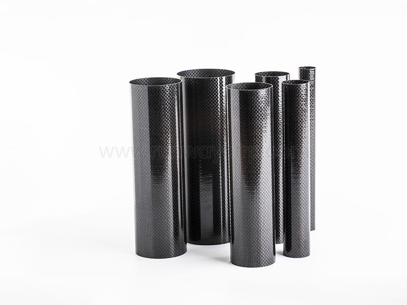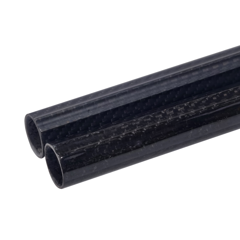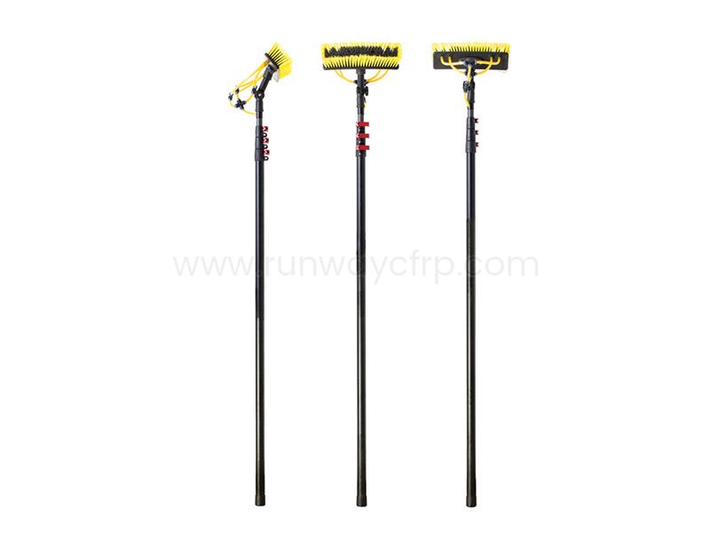
When I specify a Carbon Fiber Tube, I begin with four dimensional controls: outside diameter (OD), inside diameter (ID), wall thickness, and tolerance. OD defines the external envelope, ID defines the usable opening, wall thickness is calculated from both diameters, and tolerance describes the permitted variation from the nominal size. For example, a tube with a 30 mm OD and 26 mm ID has a nominal wall thickness of 2 mm.
!
| Specification | Meaning | Basic calculation or concern |
|---|---|---|
| OD | Outside diameter | Controls external clearance, supports, clamps, and overall envelope |
| ID | Inside diameter | Controls inserts, cables, shafts, fluid passages, and telescoping fit |
| Wall thickness | Material between OD and ID | (OD − ID) ÷ 2 |
| Tolerance | Permitted dimensional variation | Determines fit, interchangeability, and inspection limits |
| Length | End-to-end tube dimension | Affects installation, mass, deflection, and cutting allowance |
I treat carbon fiber tube specifications as an engineering description rather than a simple size label. A complete specification connects dimensions with fiber orientation, manufacturing process, load case, surface finish, length, and inspection requirements. This approach is important because two tubes with identical OD and wall thickness can behave differently if their fiber layups, resin systems, support conditions, or production methods differ.
The main dimensions affect different aspects of performance. OD and wall thickness strongly influence bending stiffness, while ID determines clearance and assembly compatibility. Length affects deflection and buckling risk, and tolerance determines whether the finished tube can be installed without excessive rework or unwanted movement.
OD means outside diameter, measured across the exterior of the tube through its center. ID means inside diameter, measured across the open internal passage. The difference between these two dimensions defines the total wall thickness across both sides of the tube.
For a round tube, OD is important when the component must fit inside a bracket, bearing, clamp, guide, or housing. ID is important when the tube must accept an insert, shaft, cable, sleeve, fastener, or another telescoping section. In telescoping systems, the ID of the larger tube must be compared with the OD of the smaller tube, including the required running clearance and manufacturing tolerance.
The wall-thickness formula is:
Wall thickness = (OD − ID) ÷ 2
For a tube with a 40 mm OD and a 34 mm ID:
Wall thickness = (40 − 34) ÷ 2 = 3 mm
This value is nominal unless the drawing also defines the dimensional tolerances. If the OD and ID vary independently, the actual wall thickness can be thinner or thicker than the nominal value. For example, an OD that is below its upper limit combined with an ID that is above its upper limit may produce a locally reduced wall thickness.
Wall thickness affects mass, stiffness, strength, impact resistance, and the ability to distribute local loads. Increasing wall thickness generally increases the section’s bending resistance, but it also increases material use and mass. For a tube subjected mainly to bending, increasing the outside diameter can produce a larger stiffness gain than adding the same amount of material near the neutral axis.
The relationship between geometry and bending stiffness is commonly evaluated through the second moment of area. For a circular tube:
I = π ÷ 64 × (OD⁴ − ID⁴)
This means diameter has a strong effect because it appears to the fourth power. A larger OD can therefore improve bending stiffness without requiring a proportionally thick wall, provided local buckling, impact, connection loads, and manufacturing limits remain acceptable.
Wall thickness also affects fit. A thicker wall reduces the ID when the OD remains fixed, which may prevent an insert from entering the tube. If the ID remains fixed, increasing wall thickness increases OD, which may interfere with external brackets or aerodynamic covers. I therefore specify the controlling dimension first according to the assembly requirement rather than choosing wall thickness in isolation.
Diameter, wall thickness, length, and cross-sectional geometry work together. A short tube may tolerate a relatively thin wall because deflection and buckling are limited, while a long slender tube may require a larger diameter, a thicker wall, additional reinforcement, or intermediate supports. The correct specification depends on whether the dominant load is bending, axial compression, tension, torsion, impact, vibration, or a combination.
Fiber orientation is equally important. Longitudinal fibers are efficient for axial loads and bending along the tube axis, while off-axis fibers contribute to torsional stiffness, hoop strength, and resistance to splitting. A tube designed only with longitudinal reinforcement may perform well in one load direction but provide limited resistance to clamp pressure or twisting.
For robotics, camera supports, inspection equipment, and drones, low mass may be a primary requirement, but the tube must still resist vibration and local attachment loads. Aerospace and structural applications require a more complete assessment of laminate design, environmental exposure, connection details, damage tolerance, and verification testing. I do not treat a published tensile or flexural value as a complete prediction of finished-part performance.
Length changes the practical behavior of the same cross-section. A long tube under compression may fail by global buckling before the composite wall reaches its material strength. A long cantilever may meet a strength requirement but fail a deflection requirement. For this reason, a tube specification should state the unsupported length, boundary conditions, applied load, load position, and allowable displacement.
A dimensional tolerance is the permitted difference between the nominal dimension and the finished dimension. If a drawing states 25.00 mm OD with a ±0.10 mm tolerance, the acceptable OD range is 24.90 to 25.10 mm. A supplier should also clarify whether the tolerance applies before or after sanding, grinding, coating, machining, or other finishing operations.
The most important tolerance categories include:
Tolerance selection should match the actual assembly need. Standard tolerances may be adequate for a noncritical support tube that is cut and drilled during assembly. Precision tolerances may be justified for telescoping sections, bearing seats, bonded inserts, or components that must be interchangeable without hand fitting. Custom tight tolerances can increase inspection, machining, rejection, and packaging costs, so I specify them only where they affect function.
A tube may meet its OD tolerance while still having poor concentricity or roundness. For example, a tube can measure 30.00 mm at several points but still have an oval cross-section or an ID that is significantly offset from the OD. A complete inspection plan should therefore define the measuring locations, gauge type, sampling frequency, and acceptance criteria.
Carbon fiber tube dimensions can be controlled accurately, but the achievable result depends on the manufacturing method, tooling, laminate design, curing process, finishing operation, and inspection system. Composite tubes may experience local variation from fiber placement, resin distribution, consolidation pressure, mandrel condition, and post-cure machining.
I distinguish between nominal dimensions and finished dimensions. A tube may be manufactured close to a target size and then reduced by sanding or grinding to meet a tighter OD requirement. Coatings, protective wraps, paint, or decorative surface treatments can increase the final OD, while internal machining can enlarge the ID.
When ordering, I state whether the required dimensions apply to the as-cured surface, sanded surface, coated surface, or final machined component. This prevents a common specification error in which the supplier and buyer measure different production stages.
The production method affects available shapes, dimensional control, fiber orientation, surface appearance, cost, and suitable load cases. I normally compare the manufacturing process with the required geometry and load instead of assuming that one method is suitable for every tube.
Roll-wrapped tubes are made by placing prepreg or resin-impregnated reinforcement around a mandrel, followed by consolidation and curing. This method allows controlled laminate schedules, including longitudinal, hoop, and angled plies. It is commonly considered when the design requires specific directional properties, a controlled surface, or a custom combination of wall thickness and fiber orientation.
The finished tube may require trimming, sanding, grinding, or machining to achieve the specified dimensions. The RFQ should state whether the quoted OD and ID are before or after these operations.
Pultruded tubes are produced by drawing continuous fibers through resin impregnation and a heated forming die. The process is efficient for constant cross-sections and long production runs. It generally suits straight profiles with consistent geometry, especially when axial stiffness and repeatable production are important.
Because the fiber direction is strongly influenced by the pulling direction, pultruded tubes should be checked carefully for torsion, hoop loading, transverse impact, and clamp compression. Additional overwraps or machined ends may be required for applications with concentrated attachment loads.
Filament winding places continuous fibers onto a rotating mandrel at controlled angles. The winding pattern can be adjusted to support axial, hoop, and torsional loads. This method is useful when the tube requires a designed fiber architecture rather than a simple unidirectional structure.
Runway identifies filament winding, roll wrapping, and pultrusion among its composite manufacturing techniques. Its product range includes carbon fiber tubes, filament-wound tubes, pultruded products, plates, rods, shapes, connectors, and telescopic poles, allowing the manufacturing method to be considered alongside the final component geometry.
Molding processes use a tool or mandrel to form the laminate, while hand lay-up places reinforcement manually before consolidation and curing. These methods can support low-volume production, larger shapes, prototypes, repairs, and complex geometries. Their dimensional consistency depends heavily on tooling accuracy, operator control, consolidation, and post-processing.
For a production tube requiring interchangeable parts, I request sample measurements and a defined inspection report before approval. For prototypes or irregular shapes, the greater process flexibility may be more useful than the tighter repeatability of a dedicated production method.
I select a tube by working from the application requirements toward the dimensions. The first question is whether the tube is primarily carrying bending, compression, tension, torsion, impact, or a combined load. The second is whether the tube must fit around another component, inside another component, or within a fixed external envelope.
Use the following selection framework:
| Application requirement | Main specification priority | Typical design concern |
|---|---|---|
| Cantilever arm | OD, length, bending stiffness | Deflection and vibration |
| Compression member | OD, wall thickness, straightness | Buckling and end loading |
| Telescoping tube | OD, ID, roundness, concentricity | Running clearance and binding |
| Shaft or insert support | ID, concentricity, end finish | Bonded or mechanical fit |
| Drone or camera structure | Mass, OD, layup, stiffness | Vibration and attachment loads |
| Fluid or cable passage | ID, ID tolerance, surface condition | Clearance and internal obstruction |
| Clamp-mounted tube | Wall thickness, local reinforcement | Crushing and splitting |
| Aerospace component | Full laminate, tolerance, inspection | Traceability and verification |
For telescoping tubes, I calculate clearance from the smallest possible ID of the outer tube and the largest possible OD of the inner tube. The available minimum clearance must also account for roundness, straightness, surface finish, contamination, temperature, and any joint or guide feature. A nominal difference that looks sufficient on paper may be inadequate after tolerance stack-up.
For clamp-mounted tubes, wall thickness alone does not determine local durability. Clamp width, bolt preload, contact radius, friction, insert design, and fiber orientation influence the risk of crushing or delamination. If a clamp applies concentrated pressure, I consider a local sleeve, bonded insert, metal interface, or additional composite reinforcement.
For structural applications, I also check mass and stiffness together. A tube that meets a static load requirement may still be unsuitable if it produces excessive deflection or resonance. I request the supplier’s laminate description, dimensional inspection method, material information, and test data that corresponds to the intended load case.
A complete request for quotation should contain more than “carbon fiber tube, 30 mm.” I include the following information:
I also identify which dimensions are function-critical. A general support tube may not require the same tolerance on every surface, while a telescoping assembly may need tighter control of OD, ID, roundness, and straightness. Separating critical from noncritical dimensions helps control cost without weakening the engineering requirement.
Before production approval, I compare the supplier’s drawing with the requested finished condition. I ask how OD, ID, wall thickness, and length are measured, at what locations, and with which instruments. I also review sample data for variation rather than accepting a single measurement as proof of process capability.
Runway, operated by Zibo Runway Composite Co., Ltd., produces composite tubes and related structural components using methods that include filament winding, roll wrapping, and pultrusion. When I evaluate a supplier for a custom tube, I would use that process range as a starting point for discussing geometry, reinforcement type, machining support, quantity, and inspection requirements. The final selection should still be based on the drawing, application load, sample results, and agreed acceptance criteria.
Carbon Fiber Tube Specifications Explained: OD, ID, Wall Thickness and Tolerance begins with four linked dimensions, but a reliable selection requires more than a size chart. I calculate wall thickness as (OD − ID) ÷ 2, then evaluate how diameter, length, fiber layup, manufacturing method, and load case affect stiffness, strength, mass, fit, and buckling risk.
I recommend specifying finished OD and ID, not only nominal mandrel dimensions, and defining whether sanding, grinding, coating, or machining occurs before final inspection. For standard supports, normal production tolerances may be sufficient; for telescoping tubes, bonded inserts, bearing fits, or interchangeable structural parts, tighter control of roundness, straightness, and concentricity may be necessary.
The practical next step is to prepare an RFQ containing the dimensions, tolerances, length, load case, surface condition, manufacturing method, and inspection requirements. By connecting the required Carbon Fiber Tube geometry to its actual assembly and structural function, I can choose a specification that is measurable, manufacturable, and suitable for production.
+86 156 9543 6852
Science & Technology Industrial Park, Zhangdian, Zibo, Shangdong, China